28
28
28
28
8
8
8
8
4
4
4
4
5
5
5
5
24
24
24
24
23
23
23
23
20
20
20
20
22
22
22
22
33
33
33
33
21
21
21
21
1
1
1
1
30
30
30
30
26
26
26
26
14
14
14
14
27
27
27
27
10
10
10
10
9
9
9
9
3
3
3
3
11
11
11
11
15
15
15
15
25
25
25
25
12
12
12
12
13
13
13
13
7
7
7
7
31
31
31
31
6
6
6
6
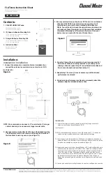
Fig. 5.21: Installation diagram for the Arkivator antenna, 99 cm, version 2012
The antenna bracket (part No. 3 and 4) is supplied assembled as per the following image. The bracket
is installed on the mast tube in a similar way to that of the Jirous antenna (point a). The bracket is ready
for tube diameters up to 115 mm. The bolts (part No. 6) should be screwed to the clamp plate (part
No. 4) in such a way that the end of the bolt protrudes approx. 6-10 mm through the other side of the
clamp plate. Saddle plates (part No. 5) are then clamped against the mast tube by tightening nuts (part
No. 7).
Warning
Before mounting the adapter (part No. 25) to be removed the green foil from the antenna
(part No. 1). This film covers the transport of the center hole in the waveguide.
After mounting the bracket on the mast tube, bolt the bent plate (part No. 2, for Arkivator 30 and 60)
or (part No. 30, for Arkivator 99) to the bracket. The actual antenna (part No. 1) is then bolted to this
plate.
43
© RACOM s.r.o. – RAy Microwave Link
Installation
Содержание RAy11
Страница 2: ......
Страница 167: ...Appendix B Rain Zone Map 167 RACOM s r o RAy Microwave Link Rain Zone Map...