a mild glass cleaner, such as "Windex" (Drackett Products Co., Cincinnati,
Ohio). Do NOT use a paper towel; do NOT use enough liquid to drip or
run.
If it should be necessary to place marks on the window, use paper-
based masking tape (NOT any kind of marking pen, which could be
abrasive or react chemically with the plastic). To minimize retention of any
gummy residue, remove the tape within a few weeks.
5.8 TROUBLE ANAL YSIS.
5.8.1 General.
CAUTION
Only well qualified personnel should attempt trouble
analysis. Be sure power is OFF during disassembly and
setting up for tests. Carefully observe the
MOS HANDLING PRECAUTIONS given in para 5.6.
Resources.
Refer to Section 4 for a good understanding of the theory of
operation. The block diagrams and discussion there provide necessary
background, which can generally save time in trouble analysis. Refer to
Section 6 for hardware details: circuit layouts, schematic diagrams, and
parts lists.
Abnormal digital signal levels.
Most digital signal levels in this
instrument are normally near zero (logic low), about +3.5 to +5 V (logic
high), or rapidly switching between these states. Failure of a digital source
often produces a dc voltage of about +2 V on a signal line. Use high-
impedance probes in measuring. Use a scope as well as a voltmeter,
because an average of 2 V may be normal for a digital signal that has a
duty cycle near 50%.
Duplicatedcircuits-.
Some circuits, as in the display board for
example, are duplicated several times. The IC's can usually be exchanged
between a faulty circuit and a functional one, to identify a "bad" IC.
Notice, also, that the resistor networks D-Z2 ...D-Z10 are simply compact
packages of 220-
Ω
resistors. If one resistor is open, it is not necessary to
replace the entire package. Use a 5% resistor.
Circuit board replacement
Refer to para 5.3 for recom
mended procedures to obtain replacements.
Telltale symptoms.
Scan the following group of symptoms for a
preliminary analysis of trouble and suggestions for more detailed
procedures if applicable.
Display. A perpetually blank digit or decimal point may be caused by a
fault in the directly associated circuit on the display board. (Refer to
comments above.)
Pushbutton. Malfunction of any pushbutton may be caused by a fault in
the switch or in buffer C-U 1 9.
Range. If one range is nonfunctional, check the corresponding switch (C-
Sl ...S3), source resistor (R 102. ..), and standard resistor (R69. ..). If range-1
measurements are inaccurate, also check the inverting amplifier in the
I- circuit, C-U46 pin 6.
D Error. A large D error on range 3 may be caused by faulty "protection"
diodes in the analog front end. Check C-CR12.. .23 (a total of 12 diodes).
D Error. If D measurements are accurate at 1 kHz but erroneous at 120
(100) Hz, fault may be in the test signal filter. Check that C-Q2 is on for low
frequency, off for
1 kHz. If so, check the test signal. (See below.)
Reactance Error. If R measurements are accurate but
C (and L) measurements are not, the test signal source may be at fault. In
checking it, as in the following paragraph, verify that the frequency is within
+/-0.0l% of the specified "actual" frequency. (See front of manual.)
Test Signal.
To check performance of the test-signal source, use a scope
to look at the open-circuit signal at the I+ terminal of the test fixture. This
should be an undistorted sine wave at the selected frequency, amplitude about
0.6 V pk-pk (+/-15%) on each range. If this is correct, skip over para 5.8.3.
Analog Front End.
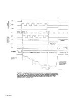
To check the entire analog front end, verify that the
signal at C-U44 pin 8 has the characteristics shown in para 5.8.4, step g,
while the instrument is measuring a DUT. If this is true for all modes
(FREQUENCY, PAR SERIES, R-L/Q-C/D, RANGES), skip to para 5.8.6.
Otherwise, check the test signal at the test fixture as outlined above.
Introduction to Detailed Analysis.
The following
trouble analysis procedures will serve as a guide for localizing a fault to a
circuit area. In some cases, a specific component part can be isolated for
replacement. I n other cases, the problem can be narrowed down only to a
circuit
board.
Except for the short-cuts indicated above, follow the procedure strictly in
the order given, doing the principal steps (a, b, c, d,. ..) until a failure is
found. Only then is there any need for the secondary steps, if any are given at
the point of failure (aa, ab, ac ...).
SERVICE 5-11
Содержание 1657 RLC Digibridge
Страница 6: ...Table of Contents...
Страница 8: ...1 2 INTRODUCTION...
Страница 9: ...INTRODUCTION 1 3...
Страница 10: ...1 4 INTRODUCTION...
Страница 15: ...OPERATION 3 1...
Страница 24: ...4 2 THEORY...
Страница 30: ...5 4 SERVICE...
Страница 42: ...5 16 SERVICE...
Страница 46: ......
Страница 49: ......
Страница 50: ......
Страница 51: ......
Страница 52: ......
Страница 53: ......
Страница 54: ......
Страница 55: ......
Страница 56: ......
Страница 57: ......


