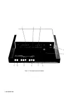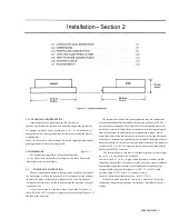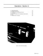
3.1 BASIC PROCEDURE. Figure 3-1.
For initial familiarization, follow this procedure care
fully. For details, refer to later paragraphs in Operation.
a. Before connecting the power cord, slide the linevoltage switch (rear
panel) to the position that corresponds to your power-line voltage. Power must
be nominally either 50 or 60 Hz ac, either 120 or 220 V. (Refer to
specifications at front of this manual.) The 1657-9700 can be run on 50 Hz but
with some loss of accuracy for 120-Hz measurements in high range
extensions. Similarly, the 1657-9800, if run
on 60-Hz power, experiences some extraneous noise in 100Hz
measurements in high range extensions.
If the fuse must be replaced, be sure to use a "slow
blow" fuse of the rating shown on the rear panel.
b. Connect a typical device, whose impedance is to be
measured, as follows. (This device under test is denoted DUT.)
NOTE
Clean the leads of the DUT if they are notice
ably dirty, even though the test-fixture contacts
will usually bite through a film of wax to pro
vide adequate connections.
Radial-lead DUT:
I nsert the leads into the test.fixture
slots as shown in the photograph, Figure 1-1. For details of wire size and
spacing limits, refer to para 3.2.
Axial-lead DUT:
Install the test-fixture adaptors, supplied, one in
each slot of the test fixture, as shown in the accompanying figure. Slide
the adaptors together or apart
so the body of the DUT will fit easily between them. Press the DUT down
so that the leads enter the slots in the adaptors as far as they go easily. For
details of wire size and DUT size limits, refer to para 3.2.
NOTE
To remove each adaptor, lift with a gentle tilt
left or right. For a DUT with very short leads
it is important to orient each adaptor so its internal contacts
(which are off center) are close
to the DUT.
Other DUTs, Remote Connections, and Bias.
For connections via extender cables and remote
test fixtures, refer to the installation instructions of paragraph 2.5. For
connection of bias voltage and operating procedures with bias, refer to
paragraphs 2.6 and 3.6. For convenience, the typical color coding used in
extender cables is repeated below.
Red: I+, current connection to "high" end of DUT. ,
Red & white: P+potential connection to same.
Black: I-, current connection to low endof DUT. .
Black & white: P-, potential connection to same
Black & Green: G, guard connection to shield or case (if isolated
from the preceding terminals). Do not-connect G to the case of a capacitor
if the case serves as (or is connected to) one of its 2 main terminals.
3-2 OPERATION
Notice that the 2 red tips must connect to the same end of the DUT. The
terminals with white bands are potential connections; with no bands, current
terminals.
c. Set.the pushbuttons according to the desired measure
ment, as follows:
Power.
Depress the POWER button so that it stays in the depressed
position. (To turn the instrument off, push and release this button so that it
remains in the released position.)
Function.
For resistance, depress R. For inductance, depress L/Q. For
capacitance, depress C/D. Be sure that one of these buttons is in the
depressed position.
Frequency.
For measurement at 1 kHz, push and release the
FREQUENCY button until the 1-kHz light comes on. For 120 (100) Hz, push
the same button so that the 120-Hz (100.Hz) light comes on.
Parallel or Series.
For series equivalent circuit, push and release the
PARALLEL/SERIES button until the SERIES light comes on. For parallel
equivalent circuit, push this button so that the PARALLEL light comes on.
(The choice is significant for lossy capacitors or inductors, not for lowloss
reactive components or non-reactive resistors.) For further explanation, refer
to para 3.5.
Range.
Depress the middle (RANGE-2) button first and watch the
ADJUST RANGE lights. If the right-pointing arrow is lighted, depress
RANGE button at the right. If the left-pointing arrow is lighted, depress
RANGE button at the left. When neither arrow is lighted, the range you have
selected is correct. (Be surc that one of the RANGE buttons is in the
depressed position.) Additional comments on range choices are below.
d. Read the measurement on the main displays. The
R LC display is the principal measurement, complete with decimal point and
units, which are indicated by the light spot behind M
Ω
, k
Ω
,
Ω
, H, mH, nF,
or uF.* The DQ display is D if the C/D FUNCTION button is in, Q if the
L/Q button is in.
e. After any change in DUT or measurement conditions, before looking
at the displays, notice the ,ADJUST RANGE
lights. Interpret them as follows:
Neither light.
Correct range. (There are minor exceptions.)
Left Light.
Wrong range; try next RANGE button to left.
Right Light.
Wrong range; try next RANGE button to
right.
Both Lights.
Overrange or invalid display. If FUNCTION is correct
and RANGE is highest, the measurement is valid but because of an
overrange condition, the basic 0.2% accuracy cannot be guaranteed. (If you
switch to RANGE 2, one
of the lights will go out.) If both lights are lit on RANGE 2, either the
FUNCTION is inappropriate for the DUT or it is not properly connected.
For more details, refer to para 3.3.
*If the extender cable is used. it may be necessary to correct for its
capacitance.
Содержание 1657 RLC Digibridge
Страница 6: ...Table of Contents...
Страница 8: ...1 2 INTRODUCTION...
Страница 9: ...INTRODUCTION 1 3...
Страница 10: ...1 4 INTRODUCTION...
Страница 15: ...OPERATION 3 1...
Страница 24: ...4 2 THEORY...
Страница 30: ...5 4 SERVICE...
Страница 42: ...5 16 SERVICE...
Страница 46: ......
Страница 49: ......
Страница 50: ......
Страница 51: ......
Страница 52: ......
Страница 53: ......
Страница 54: ......
Страница 55: ......
Страница 56: ......
Страница 57: ......

