If your line voltage is in the higher range selectable by the line voltage
switch, use a power cord of the proper rating (250 V, 15 A) that mates
with both instrument and
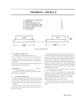
your receptacle. It is possible to replace the "hammerhead" connector on the
power cord that is supplied with a suitable connector. Be sure to use one
that is approved for 250 V, 15 A. A typical configuration is shown in Figure
2-2.
2.4 LINE-VOLTAGE REGUlATION
The accuracy of measurements accomplished with precision electronic
test equipment operated from ac line
sources can often be seriously degraded by fluctuations in primary input
power. line-voltage variations of +/-15% are commonly encountered, even
in laboratory environments.
Although most modern electronic instruments incorporate some degree of
regulation, possible power.source problems should be considered for
every instrumentation setup. The use of line-voltage regulators between
power lines and the
test equipment is recommended as the only sure way to rule out the effects
on measurement data of variations in line voltage.
2.5 TEST-FIXTURE CONNECTIONS
.
2.5.1 Test Fixture on the Digibridge.
Because an unusually versatile test fixture is provided on the front shelf
of the instrument, no test-fixture connection is generally required. Simply
plug the device to be measured (DUT) into the test fixture, with or without
its adaptors. For details, refer to paragraphs 3.1, 3.2. Accessories can be
attached to extend and adapt the test fixture, as described below.
2.5.2 Remote Test Fixture.
Connection of the DUT at a remote test fixture requires proper adaptors
and cable connections from the Digibridge. Obtain the following
accessories. (See Table 1-3.)
BNC Adaptor 1689-9601
BNC Cable Assembly 1689-9602, or equivalent
Remote Test Fixture 1689-9600, or equivalent
handler or special fixture.
This remote test fixture functions like the one supplied on the
Digibridge. True "Kelvin" connections are made at the points of contact
with the DUT leads. Install as
follows:
a. Remove any adaptors, if present, from the test
fixture.
b. Plug the BNC adaptor into the basic test fixture with the BNC
connectors facing forward. lock the connection with the 2 captive thumb
screws. (The screws must be
seated to complete the ground connection.)
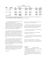
c. Connect the cable assembly to the adaptor on the Digibridge and to
the remote test fixture as indicated in Table 2-1.
NOTE
User provided cables and/or remote test
fixtures can be used, particularly if the
DUT is to
be handled automatically.
See paragraph 3.7 for comments on cable
and fixture capacitance.
2.5.3 The 1657-9600 Extender Cable (Banana Plugs).
The accessory extender cable 1657-9600 is available
to
connect to
DUTs that are multiterminal, physically large, or otherwise unsuited for
the built-in test fixture. This cable is particularly convenient for connecting
multiterminal components with binding posts that accommodate banana
plugs. Use the following procedure to install the extender cable on the
instrument.
a. Remove the adaptors, if present, from the test
fix tu re.
b. Plug the single-connector end of the extender cable into the
Digibridge test fixture so that its blades enter both slots and the cable lies
away from the display panel. lock the connector with the
two
captive
thumb screws.
c. Note the color coding of the five banana plugs. Be sure that the
"low" terminals (both potential and current)
connect
to one end of the
DUT and the "high" terminals to the other end. Connect guard to a shield if
any, but not to either end of the DUT.
2-2 INSTAllATION
Содержание 1657 RLC Digibridge
Страница 6: ...Table of Contents...
Страница 8: ...1 2 INTRODUCTION...
Страница 9: ...INTRODUCTION 1 3...
Страница 10: ...1 4 INTRODUCTION...
Страница 15: ...OPERATION 3 1...
Страница 24: ...4 2 THEORY...
Страница 30: ...5 4 SERVICE...
Страница 42: ...5 16 SERVICE...
Страница 46: ......
Страница 49: ......
Страница 50: ......
Страница 51: ......
Страница 52: ......
Страница 53: ......
Страница 54: ......
Страница 55: ......
Страница 56: ......
Страница 57: ......

