2.1 UNPACKING AND INSPECTION.
If the shipping carton is damaged, ask that the carrier's
agent be present when the instrument is unpacked. Inspect the instrument
for damage (scratches, dents, broken parts, etc.). If the instrument is
damaged or fails to meet specifications, notify the carrier and the nearest
GenRad field
office. (See list at back of this manual). Retain the shipping carton and the
padding material for the carrier's inspection.
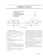
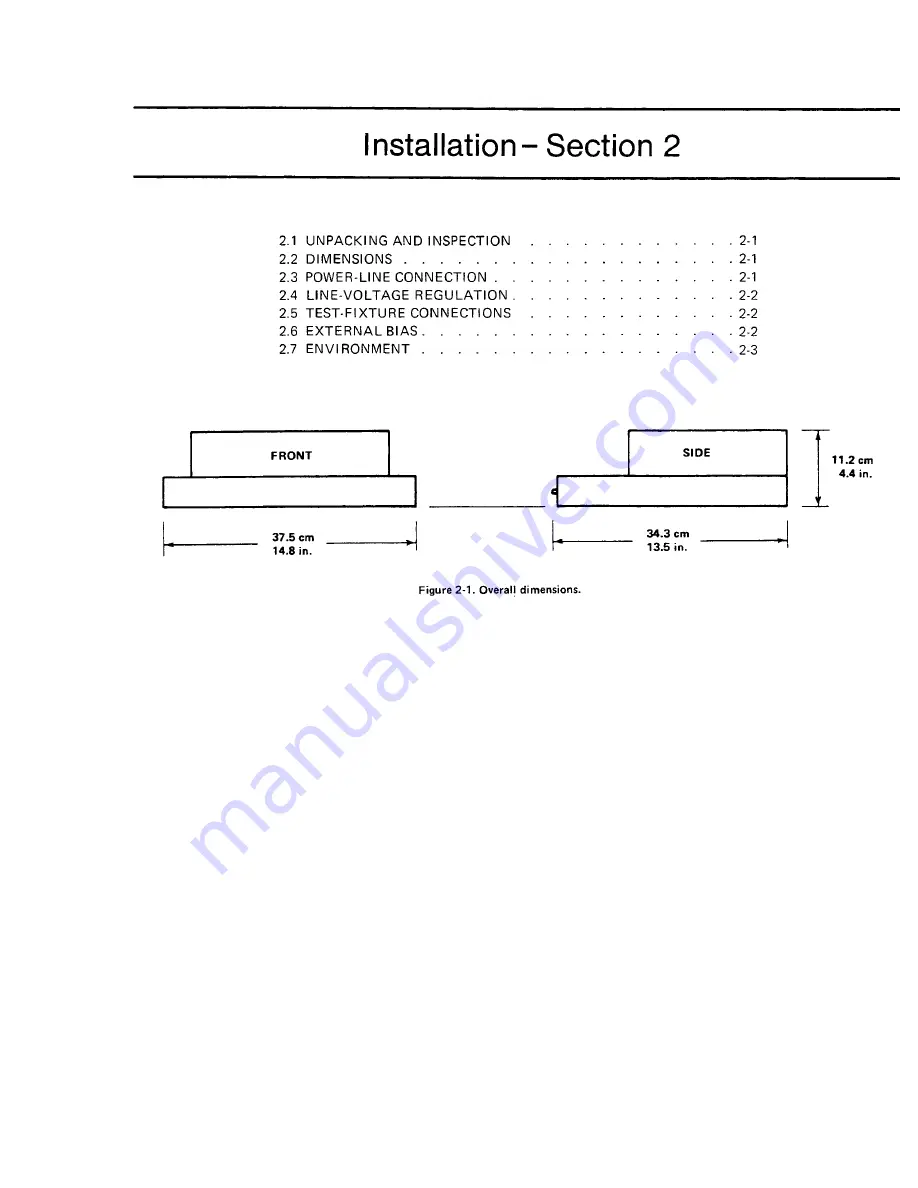
2.2 DIMENSIONS
Figure 2-1.
The instrument is supplied in the bench configuration,
i.e., in a cabinet with resilient feet for placement on a table. The overall
dimensions are given in the figure.
2.3 POWER-liNE CONNECTION.
The power transformer primary windings can be switched, by means of
the line voltage switch on the rear panel, to ac. commodate ac line voltages
in either of 2 ranges, as labeled, at a frequency of 50 or 60 Hz, nominal.
Using a small screwdriver, set this switch to match the measured voltage of
your power line.
I f your I ine voltage is in the lower range, connect the 3-wire power
cable (P/N 4200-9625) to the power connector on the rear panel (Figure 1-2)
and then to the power line.
The instrument is fitted with a power connector that is in conformance
with the International Electrotechnical Commission publication 320. The 3
flat contacts are surrounded by a cylindrical plastic shroud that reduces the
possibility of electrical shock whenever the power cord is being unplugged
from the instrument. In addition, the center ground pin is longer, which
means that it mates first and disconnects last, for user protection. This panel
connector is a standard 3-pin grounding-type receptacle, the design of which
has been accepted world wide for electronic instru. mentation. The connector
is rated for 250 V at 6 A. The receptacle accepts power cords fitted with the
Belden type SPH-386 connector.
The associated power cord for use with that receptacle, for line voltages
up to 125 V, is Gen Rad part no. 4200-9625.
It is a 210-cm (7 ft), 3-wire, 18-gage cable with connector bodies molded
integrally with the jacket. The connector at the power-line end is a stackable
hammerhead design that conforms to the "Standard for Grounding Type
Attachment Plug Caps and Receptacles," ANSI C73. 11-1966, which
specifies limits of 125 V and 15 A. This power cord is
listed by Underwriters Laboratories, Inc., for 125 V, 10 A.
If the fuse must be replaced, be sure to use a "slow blow" fuse of the
current and voltage ratings shown on the rear panel, regardless of the line
voltage.
INSTAllATION
2-1
Содержание 1657 RLC Digibridge
Страница 6: ...Table of Contents...
Страница 8: ...1 2 INTRODUCTION...
Страница 9: ...INTRODUCTION 1 3...
Страница 10: ...1 4 INTRODUCTION...
Страница 15: ...OPERATION 3 1...
Страница 24: ...4 2 THEORY...
Страница 30: ...5 4 SERVICE...
Страница 42: ...5 16 SERVICE...
Страница 46: ......
Страница 49: ......
Страница 50: ......
Страница 51: ......
Страница 52: ......
Страница 53: ......
Страница 54: ......
Страница 55: ......
Страница 56: ......
Страница 57: ......

