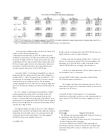
The logarithmic scales on these figures make it very easy to apply the
accuracy factors
visually.
For example, suppose a capacitor is being measured
on range 2, both ADJUST RANGE lights are out, and the D display' is about
1. Figure 3-3 shows that the C accuracy factor is about 1/3 of a decade on the
logarithmic scale. On Figure 3-2, find the heavy dotted line (the basic portion
of range 2) and point to the basic C accuracy (0.2%) at the left. Now apply the
C accuracy factor by moving the pointer up about 1/3 of a decade. The pointer
now shows the corrected C accuracy, 0.4%.
3.4.2 Insignificant Digits.
One or more of the digits at the right end of the R LC and/or DQ displays
may be insignificant. This is particularly true at the upper extension of a
range. If there are more than one insignificant digits in a display, the least
significant is typically noisy. That is, it will appear to flicker at random over a
range of values and should be ignored.
For example, if you measure a 4-M
Ω
resistor, the display might ideally
be 4.1234 M
Ω
; but the one or two final digits might be changing at random.
This flickering is entirely normal. The specified accuracy (+/-0.4%) is the key
to expected performance; in this example, the last 2 digits are insignificant
and the last digit is quite unnecessary. Typically, one would record this
measurement as 4.12 +/-.02 M
Ω
.
3.5 PARALLEL/SERIES AND FREQUENCY SELECTIONS.
3.5.1 General.
The value of the principal measurement (R, L, or C) of a certain DUT
depends on which of 2 equivalent circuits is chosen to represent it. (Many
impedance measuring instruments provide no choice in the matter, but this
one allows selection.) The more nearly "pure" the resistance or reactance, the
more nearly identical are the "series" and "parallel" values. However, for D
or 0 near unity, the difference is substantial. Also, the principal measurement
often depends on measurement frequency. The more nearly "pure" the
resistance or reactance, the less is this dependence. However, for D or Q near
unity and/or for measuring frequency near the self-resonant frequency of the
DUT, this dependence
is quite substantial. We first give general rules for selection of measurement
parameters, then some of the theory.
3.5.2 Rules.
Specifications.
The manufacturer or principal user of the DUT probably
specifies how to measure it. (Usually "series" is specified for C, L, and low
values of R.) Select "parallel"
or:
"series" and 1 kHz or 120 Hz (100 Hz)
according to the applicable specifications. If there are none known, be sure
to
3-6 OPERATION
specify with your results whether they are "parallel" or "series" and what the
measurement frequency was.
Resistors, below about
1
k
Ω
: Series, 120 Hz (100 Hz).
Usually the
specifications call for dc resistance, so select a low test frequency to
minimize ac losses. Select "series" because the reactive component most
likely to be present in a low-resistance resistor is series inductance, which
has no effect on the measurement of series R. As a quick check on whether
the DUT is nearly pure resistance, make a separate "parallel" measurement.
Rp will be larger then Rs. If the difference is less then 1 %, then 0 is less
than 0.1, and the measured Rs is probably very close to the dc resistance.
Resistors, above about
1
k
Ω
: Parallel, 120 Hz (100 Hz).
As
explained above, select a low test frequency. Select "parallel" because the
reactive component most likely to be present in a high-resistance resistor is
shunt capacitance, which has no effect on the measurement of parallel R. As
a quick check on whether the DUT is nearly pure resistance, make a
separate "series" measurement. If the difference between Rp and Rs is less
than 1%, then D is greater than 10, and the measured Rp is probably very
close to the dc resistance.
Capacitors below
2
nF: Series,
1
kHz.
Unless otherwise specified or for
special reasons, always select "series"
for capacitors and inductors. This has traditionally been standard practice.
Select a high measurement frequency for best accuracy.
Capacitors above 200 uF: Series, 120 Hz (100 Hz).
Select "series" for
the reasons given above. Select a low measurement frequency for best
accuracy and to enable measurement of capacitors larger than 1000uF.
Inductors below
2
mH: Series,
1
kHz.
Select "series"
as explained above. Select a high measurement frequency for best accuracy.
Inductors above 200 H: Series, 120 Hz (100 Hz).
Select "series" as
explained before. Select a low measurement frequency for best accuracy
and to enable measurement of inductors larger than 1000 H.
3.5.3 Series and Parallel Parameters. Figure 3-5.
An impedance that is neither a pure reactance nor a pure resistance can
be represented at any specific frequency by either a series or a parallel
combination of resistance and reactance. Keeping this concept in mind will
be valuable
in operation of the instrument and interpreting its measurements. The values
of resistance and reactance used in the equivalent circuit depend on whether
a series or parallel combination is used. The equivalent circuits are shown in
Figure 3-5. The relationships between the various circuit elements are as
follows.
Содержание 1657 RLC Digibridge
Страница 6: ...Table of Contents...
Страница 8: ...1 2 INTRODUCTION...
Страница 9: ...INTRODUCTION 1 3...
Страница 10: ...1 4 INTRODUCTION...
Страница 15: ...OPERATION 3 1...
Страница 24: ...4 2 THEORY...
Страница 30: ...5 4 SERVICE...
Страница 42: ...5 16 SERVICE...
Страница 46: ......
Страница 49: ......
Страница 50: ......
Страница 51: ......
Страница 52: ......
Страница 53: ......
Страница 54: ......
Страница 55: ......
Страница 56: ......
Страница 57: ......


