Each basic range is slightly more than 2 decades wide, from an R LC
display of 01900, with an automatic decimal
point change between the decades, to 19999. (The symbol 0 represents
a blanked zero. Initial zeroes to left of the decimal point are always blanked
out of the RLC display.) Each of the 3 ranges goes beyond its basic range,
with both upper and lower range extensions (shown by lighter lines in the
RLC basic accuracy graph). Several of these extensions are seldom used
because they overlap "basic" portions of other ranges and because the
operator is alerted to this fact by an ADJUST RANGE light.
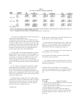
Each range includes 2 or 3 subranges, distinguished by the automatic
decimal-point shift. The operator does NOT control them. Subranges are
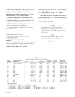
detailed in Table 3-1. Notice, for example, if you select RANGE 1, C/D, 1
kHz, then there are 2 subranges: 19uF and 999uF. If a series of measure-
ments is made with C increasing slowly above 19uF, the automatic
subrange change takes place at 21. But with C decreasing, the change takes
place at 20. This hysteresis eliminates a possible cause of flickering of the
display.
The "low" extension of each range goes from 01900 down to 00000,
without any change in decimal point, but with reduced accuracy. The
number of digits in this display is always adequate for the specified
accuracy. Any measurement in the low extension of either Range 2 or the
highest range causes the appropriate ADJUST RANGE arrow to be lighted.
But there is no such light in the low extension of the lowest range (because
there is no lower range to select).
The "high" extension of each range is a factor of 5 (with 2 exceptions),
going from 19999 up to 99999, and finally to blank, without any change in
decimal point, but with reduced accuracy. Any measurement in the high
extension of either the lowest range or Range 2 causes the appropriate
ADJUST RANGE arrow to be lighted. However in
3-4 OPERATION
the high extension of the highest range, both ADJUST RANGE arrows are
lighted (to indicate a useful "overrange" condition) .
The high extension of the top range for Rand C only, at 120 Hz (100
Hz) only, is a factor of 50, going from 19999, with an automatic decimal-
point change, up to 99999, and finally to blank, with reduced accuracy.
(Both ADJUST RANGE arrows are lighted as described above.)
A special case warrants explanation. (This is a minor exception to the
basic procedure of para 3.1.) It is possible
for both ADJUST RANGE lights to be out and yet the RANGE and
FUNCTION buttons to be incorrectly set.
This condition result's from either faulty connection to the DUT or a
numerically small negative Lor C measurement. Sometimes a loose or dirty
connection to the DUT causes
an erratic RLC display. A small negative L or C (wrong function
selected) causes a zero display. In either case, check connections at the test
fixture and try all 3 FUNCTIONS to see which is appropriate, R, L/Q, or
C/D.
3.4 ACCURACY.
3.4.1 Graphs. Figures 3-2, 3-3, and 3.4
The following accuracy graphs supplement the statement of accuracy in
the specifications, at the front of this manual.
Figure 3.2 shows that the R LC basic accuracy of 0.2% is realized over
6 decades of impedance if the correct range
is selected (as indicated by the ADJUST RANG E lights being out).
The reduction of accuracy is shown for all of the "low" and "high" range
extensions. This basic RLC accuracy is valid only for "pure" R. L, or C.
For the effect
Содержание 1657 RLC Digibridge
Страница 6: ...Table of Contents...
Страница 8: ...1 2 INTRODUCTION...
Страница 9: ...INTRODUCTION 1 3...
Страница 10: ...1 4 INTRODUCTION...
Страница 15: ...OPERATION 3 1...
Страница 24: ...4 2 THEORY...
Страница 30: ...5 4 SERVICE...
Страница 42: ...5 16 SERVICE...
Страница 46: ......
Страница 49: ......
Страница 50: ......
Страница 51: ......
Страница 52: ......
Страница 53: ......
Страница 54: ......
Страница 55: ......
Страница 56: ......
Страница 57: ......

