background image

Reference 

MVI56-PDPMV1 ♦ ControlLogix Platform 

User Manual 

PROFIBUS DPV1 Master 

Page 236 of 251 

ProSoft Technology, Inc.  

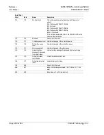
Byte Offset 
Start 

End 

Name 

Description 

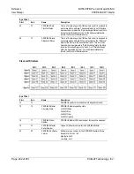
118 

119 

File Error Word 

This is bit-mapped value that indicates which files are not 
present. 
Bit 0: Problem with PDPMV1.CFG file 
Bit 1: Not used 
Bit 2: Problem with PDPMV1.DDB file 
Bit 3: Problem with PDPMV1.XML file 
Bits 4 to 15 not used. 
If this word has a value other than 0, the CFG ERR LED on the 

module will be illuminated. 

120 

145 

Reserved 

Reserved for future use 

146 

147 

In mailbox queue count  Number of message in the in mailbox queue 

148 

149 

Out mailbox queue 
count 

Number of message in the out mailbox queue 

150 

151 

Alarm queue count 

Number of message in the alarm queue 

152 

153 

Last out mailbox 
message ID processed 

from output image 

Last out mailbox message ID processed from output image 

154 

155 

Current in mailbox 
control index 

Current in mailbox control index 

156 

157 

Current alarm control 

index 

Current alarm control index 

158 

496 

Reserved for future use 

496 

497 

Index of Output image to receive (1 to 4 for data, 0 or -1 if no 
data) 

498 

499 

Block index of -1 or 0 for status block 

Содержание MVI56-PDPMV1

Страница 1: ...MVI56 PDPMV1 ControlLogix Platform PROFIBUS DPV1 Master August 5 2021 USER MANUAL...

Страница 2: ...l Code for installations in Canada and in accordance with the authority having jurisdiction The following warnings must be heeded WARNING EXPLOSION HAZARD SUBSTITUTION OF COMPONENTS MAY IMPAIR SUITABI...

Страница 3: ...ly twenty hours before the battery becomes fully charged After it is fully charged the battery provides backup power for the CMOS setup and the real time clock for approximately 21 days When the batte...

Страница 4: ......

Страница 5: ...1 Choosing the Controller Type 66 1 8 2 Selecting the Slot Number for the Module 69 1 8 3 Selecting the Connection Parameters for the Module 69 1 8 4 Selecting the RPI Time for the Module 71 1 8 5 Cha...

Страница 6: ...onfiguration 152 3 5 4 Mailbox Message Set Slave Address 154 3 5 5 Mailbox Message Get Live List 156 3 5 6 Mailbox Message Class 1 Acyclic Data Read 158 3 5 7 Mailbox Message Class 1 Acyclic Data Writ...

Страница 7: ...nication Rate 201 5 2 5 PROFIBUS Master Port 202 5 2 6 Constructing a Bus Cable for PROFIBUS DP 203 5 2 7 Supported PROFIBUS Services 208 5 3 PROFIBUS comDTM 209 5 3 1 ProSoft Technology Product Avail...

Страница 8: ...MVI56 PDPMV1 ControlLogix Platform PROFIBUS DPV1 Master User Manual Page 8 of 251 ProSoft Technology Inc...

Страница 9: ...complete the steps in this chapter before developing a custom application After you have verified that the module is installed and communicating successfully with the processor and the PROFIBUS netwo...

Страница 10: ...allation the module requires Ethernet I P or ControlNet access to the processor 1 2 Package Contents The following components are included with your MVI56 PDPMV1 module and are all required for instal...

Страница 11: ...ame contains the version of PCB For example PCB_4 1 0 4 0206 exe To install ProSoft Configuration Builder from the ProSoft Technology website 1 Open your web browser and navigate to www prosoft techno...

Страница 12: ...lan to connect to verify that suitable safety procedures are in place before installing or servicing the device Warning When you insert or remove the module while backplane power is on an electrical a...

Страница 13: ...ic sample programs For applications with ControlLogix firmware version 16 or newer you can use the supplied L5X AOI files which encapsulate the ladder logic controller tags and user defined data types...

Страница 14: ...d RSLogix documentation for help configuring and troubleshooting these applications 1 Connect an RS 232 serial cable from the COM serial port on your PC to the communication port on the front of the p...

Страница 15: ...firmware version Checking the Version During Power Up When the module powers up it will search for the ControlLogix processor to establish backplane connectivity If the correct ladder is not loaded to...

Страница 16: ...ProSoft Technology Inc If the message MVI56 PDPMV1 Firmware Version x xx appears on the screen as shown in the following illustration the module firmware is version 1 21 or later If the message MVI56...

Страница 17: ...Y or FLEX is loaded into your processor and the module is located in same slot that was configured then after module power up it will be possible to access the debug menu through ProSoft Configuration...

Страница 18: ...ons Since all parameters are fixed configuration is simpler than FLEX mode Status data is bought across the backplane as I O data without the need for additional logic to trigger MSG instructions FLEX...

Страница 19: ...ions 15 and earlier do not support Add On Instructions so do not try to import the AOI L5K files into those older versions of RSLogix 5000 For ControlLogix firmware version 16 or newer refer to Using...

Страница 20: ...application 6 Manually copy the ladder logic tasks and rungs from the sample program and paste them into your existing application 1 7 Using the MVI56 PDPMV1 Add On Instruction Note This section appli...

Страница 21: ...ou Begin The following file is required before you start this procedure You can download it from www prosoft technology com File Name Description MVI56PDPMV1_LEGACY_AddOn_Rung_ L5X where is the curren...

Страница 22: ...VI56 PDPMV1 module to the project In the Controller Organization window select I O CONFIGURATION and click the right mouse button to open a shortcut menu On the shortcut menu choose NEW MODULE This ac...

Страница 23: ...the module Example ProSoft communication module for PROFIBUS communication Comm Format Select DATA INT Slot Enter the slot number in the rack where the MVI56 PDPMV1 module is located Input Assembly In...

Страница 24: ...ng Import files For additional information on how to export custom made L5X files from PCB please see Exporting the Processor Files Prior to PCB v2 2 0 page 102 1 Open your application in RSLogix 5000...

Страница 25: ...251 ProSoft Technology Inc 6 Select the MVI56PDPMV1_LEGACY_v ACD standard sample file or the MVI56PDPMV1_LEGACY_AddOn_Rung_v L5X custom file you exported from PCB and click the IMPORT button 7 A windo...

Страница 26: ...ou are using the module in a different slot or remote rack select the correct connection input and output variables to provide the correct path to the module If your module is located in Slot 1 of the...

Страница 27: ...roSoft Technology Inc 10 When the import is completed the new rung with the Add On Instruction will be visible as shown in the following illustration The procedure has also imported new user defined d...

Страница 28: ...hnology Inc Adding Multiple Modules Optional Legacy Important If your application requires more than one MVI56 PDPMV1 module into the same project follow the steps below 1 In the I O Configuration fol...

Страница 29: ...Enter the number of words per backplane input block to copy from the module to the processor The allowable range is from 12 to 250 words Each input block will reserve 8 words for general purposes CRC...

Страница 30: ...nProgram folder click the right mouse button to open a shortcut menu On the shortcut menu choose NEW ROUTINE 7 In the New Routine dialog box enter the name and description of your routine and then cli...

Страница 31: ...ter User Manual Page 31 of 251 ProSoft Technology Inc 10 The following window will be displayed showing the tags to be imported 11 Associate the I O connection variables to the correct module The defa...

Страница 32: ...logy Inc 12 Change the default tags MVI56PDPMV1 and PS56PDPMV1 to avoid conflict with existing tags by append the string _2 or any other unique identifier string as follows 13 Click OK to confirm The...

Страница 33: ...defined data types provided with the sample ladder logic are critical to incorporating the MVI56 PDPMV1 into your application Legacy Mode Note You cannot perform this procedure while you are online t...

Страница 34: ...and and then click OK This action opens the Module Properties dialog box 4 In the Module Properties dialog box enter the NAME DESCRIPTION and SLOT options for your application using the examples in th...

Страница 35: ...n in the following illustration 6 Click FINISH to save the module into your existing application 7 Next open the sample program in RSLogix 5000 Refer to Choosing Sample Ladder Logic For Your Applicati...

Страница 36: ...251 ProSoft Technology Inc 9 Copy and paste each of the user defined types from the sample ladder logic into your existing application 10 Export the controller tags from the sample program Tools Expor...

Страница 37: ...rameters may assume values within the following ranges Minimum Size 16 bit Maximum Size 16 bit Maximum PROFIBUS data count per block 16 bit Assembly Instance Input 12 250 input size 8 1 Output 5 248 b...

Страница 38: ...the following user defined data types PDPMV1_CONNECTION_INPUT PDPMV1_CONNECTION_OUTPUT You will also need to adjust limits in some of the ladder logic or AOI logic For additional details see Adjusting...

Страница 39: ...an array size of 248 words as shown in the following illustration Note Each backplane block contains certain registers reserved for general purposes non PROFIBUS data transfer The backplane input bloc...

Страница 40: ...ny of the following it will be done for you already If this is the case all you need to do is import the custom L5X file according to the procedure found in Importing the Ladder Rung Flex page 52 For...

Страница 41: ...User Manual Page 41 of 251 ProSoft Technology Inc 3 Adjust the array size for your application The default array size is INT 250 maximum size This example is for 250 input words 4 In the DATA TYPES U...

Страница 42: ...Count 250 words Output Count 248 words If different values are used make the following changes to the ladder logic COP Instruction input Change the Length to match the number of input words configure...

Страница 43: ...e The default uses 248 words Example FLEX application For this example if your application requires the PROFIBUS total data sizes configured as follows through the ProSoft Configuration Builder PROFIB...

Страница 44: ...ne backplane I O block The module will generate two block IDs blocks 0 and 1 in order to force a Block ID switch as required for the ladder logic to function correctly but both blocks will contain the...

Страница 45: ...data Note For this scenario block 0 is no longer required because there are two backplane blocks with different data Backplane Block Overview Block Number Input Output Total word count in backplane b...

Страница 46: ...lane output blocks will be required Backplane Block Overview Block Number Input Output Total word count in backplane block PROFIBUS Data Word Count in backplane block Initial PROFIBUS Data Word Offset...

Страница 47: ...output blocks will be required Backplane Block Overview Block Number Input Output Total word count in Backplane block PROFIBUS Data Word Count in backplane block Initial PROFIBUS Data Word Offset in...

Страница 48: ...10 Output 15 10 90 99 Note This configuration would be extremely inefficient and is therefore not recommended The first example Scenario 1 is a more efficient configuration that will accomplish the s...

Страница 49: ...ogix Platform Start Here PROFIBUS DPV1 Master User Manual Page 49 of 251 ProSoft Technology Inc Creating the MVI56 PDPMV1 Module Profile Flex 1 Right click I O CONFIGURATION and then choose NEW MODULE...

Страница 50: ...k to copy from the module to the processor The allowable range is from 12 to 250 words Each input block will reserve 8 words for general purposes CRC block CIP handshaking The remainder is reserved fo...

Страница 51: ...ere the processor is located or in a remote rack connected through EtherNet IP adapters select the maximum value of 750 MS o If the module is located in a remote rack connected through ControlNet adap...

Страница 52: ...t Technology Inc Importing the Ladder Rung Flex 1 Open your application in RSLogix 5000 2 Expand the Tasks folder and then expand the MainTask folder 3 In the MainProgram folder select an empty rung a...

Страница 53: ...sample file or the MVI56PDPMV1_FLEX_AddOn_Rung_v L5X custom file you exported from PCB and click the IMPORT button 5 The following window will be displayed showing the controller tags associated with...

Страница 54: ...m User Manual PROFIBUS DPV1 Master Page 54 of 251 ProSoft Technology Inc 6 If your module is located in a different slot or in a remote rack modify the parameters to set the correct path to the module...

Страница 55: ...logy Inc 8 The new rung will be now visible in the ladder logic showing also the PS56PDPMV1_FLEX Add On Instruction 9 The procedure has also imported new user defined data types controller tags and co...

Страница 56: ...chnology Inc Adding Multiple Modules Optional Flex Important If your application requires more than one MVI56 PDPMV1 module into the same project follow the steps below 1 In the I O Configuration fold...

Страница 57: ...ch input block will reserve 8 words for general purposes CRC block CIP handshaking The remainder is reserved for PROFIBUS input data Output Assembly Instance 2 Output Size Enter the number of words pe...

Страница 58: ...gy Inc 8 Select an empty rung in the new routine and then click the right mouse button to open a shortcut menu On the shortcut menu choose IMPORT RUNG 9 Select the PS56PDPMV1_FLEX_v L5X standard sampl...

Страница 59: ...MVI56 PDPMV1 ControlLogix Platform Start Here PROFIBUS DPV1 Master User Manual Page 59 of 251 ProSoft Technology Inc 10 The following window will be displayed showing the tags to be imported...

Страница 60: ...ROFIBUS DPV1 Master Page 60 of 251 ProSoft Technology Inc 11 Change the names of all controller tags to avoid a conflict with the existing names In this step you should append a string to the default...

Страница 61: ...gix Platform Start Here PROFIBUS DPV1 Master User Manual Page 61 of 251 ProSoft Technology Inc 12 For the connection I O variables select the variables associated to the correct module as follows Inpu...

Страница 62: ...Start Here MVI56 PDPMV1 ControlLogix Platform User Manual PROFIBUS DPV1 Master Page 62 of 251 ProSoft Technology Inc Output Connection Variable 13 Click OK to confirm the import procedure...

Страница 63: ...rung will now be visible in the ladder logic 15 The module name associated with the project uses a different name than the standard MVI56PDPMV1 You must re define the path accordingly for each MESSAG...

Страница 64: ...64 of 251 ProSoft Technology Inc 16 Select the BROWSE button and select the correct module to be associated to the MESSAGE instruction Click OK to confirm 17 Click OK to confirm the MESSAGE configurat...

Страница 65: ...ControlLogix Platform Start Here PROFIBUS DPV1 Master User Manual Page 65 of 251 ProSoft Technology Inc The setup procedure is now completed and the processor is ready to communicate with the MVI56 P...

Страница 66: ...of your specific custom application 1 8 1 Choosing the Controller Type This sample application shows a 1756 L63 ControlLogix 5563 Controller selected If you are using a different model of the Control...

Страница 67: ...PDPMV1 ControlLogix Platform Start Here PROFIBUS DPV1 Master User Manual Page 67 of 251 ProSoft Technology Inc 2 On the shortcut menu choose PROPERTIES This action opens the Controller Properties dial...

Страница 68: ...CONTROLLER button This action opens the Change Controller dialog box 4 Open the TYPE drop down list and then select your ControlLogix controller 5 Select the correct firmware revision for your control...

Страница 69: ...f the field to select the slot number where the module will reside in the rack and then click OK RSLogix will automatically apply the slot number change to all tags variables and ladder logic rungs th...

Страница 70: ...Soft Configuration Builder for modules with firmware version 1 21 or later only Note that the parameters that are displayed on the Edit screen vary depending on whether YES or NO is selected for the U...

Страница 71: ...fer to the Connection tab and enter the RPI time The connection is scheduled to move data to or from the module at least this often The RPI time to enter depends on your application as follows RPI Tim...

Страница 72: ...ue MVI56 PDPMV1 module firmware version 1 21 or later MVI56 PDPMV1 module configured in FLEX mode USE LEGACY MODE NO MVI56 PDPMV1 module is located in either the local rack or remote rack through Ethe...

Страница 73: ...logic must be manually deleted before the new rung export file can be successfully imported Failure to follow this procedure may result in the module becoming non functional This procedure assumes yo...

Страница 74: ...V1 ControlLogix Platform User Manual PROFIBUS DPV1 Master Page 74 of 251 ProSoft Technology Inc 2 Go to the Controller Tags window and select the EDIT TAGS tab DELETE all the controller tags associate...

Страница 75: ...s created by the original import 4 Go to the Data Types folder to the User Defined sub folder DELETE the following user defined data types in the following order a PDPMV1_Connection_Input b PDPMV1_Con...

Страница 76: ...r in PCB is used to create a communication path for the Status and Acyclic Data MSG instructions If the two names are not identical the import may appear to have completed successfully but the module...

Страница 77: ...stablish communication with the processor 3 When communication is established RSLogix opens a confirmation dialog box Click the DOWNLOAD button to transfer your project to the processor 4 RSLogix will...

Страница 78: ...ect your PC to the Configuration Debug port using the RJ45 DB 9 Serial Adapter Cable and the Null Modem Cable included in the package with the MVI56 PDPMV1 module 1 Connect the RJ45 DB 9 Serial Adapte...

Страница 79: ...oject to the Module 107 Verifying Correct Operation 119 Because the task of configuring the PROFIBUS network can be challenging ProSoft Technology has provided a configuration tool called ProSoft Conf...

Страница 80: ...onsists of folders for Default Project and Default Location with a Default Module in the Default Location folder Start by adding the MVI56 PDPMV1 module to the project 1 Use the mouse to select DEFAUL...

Страница 81: ...In the following steps you will provide the missing information to make the red X s go away 1 Click the plus sign next to the module to expand the module tree and then expand the MVI PDPM V1 tree 2 D...

Страница 82: ...ed as follows If you chose a FLEX sample Set USE LEGACY MODE NO If you chose a LEGACY sample Set USE LEGACY MODE YES 4 Click OK to save your settings and return to the main PCB window At this time you...

Страница 83: ...alog box 2 In the PDPMV1 PROFIBUS Master Setup dialog box click the CONFIGURE PROFIBUS button This action opens the ProSoft Configuration Builder for PROFIBUS application 3 Click to expand the PROFIBU...

Страница 84: ...are already installed GSD files are often both model number specific as well as model revision specific Just because you may have an older GSD file from a manufacturer for the particular make and mode...

Страница 85: ...B or the configuration tool supplied by the manufacturer for some PROFIBUS slaves Verify that the slave address configured in the slave module matches the slave address configured in PCB Download the...

Страница 86: ...ster in a network relationship 4 In the tree view click the plus sign to expand the slave device you added This action opens a list of device configuration values The following illustration shows the...

Страница 87: ...network For this example we will configure thirty two 32 words of output and eight 8 words of input These input and output words are assigned to addresses within the MVI56 PDPMV1 module s internal dat...

Страница 88: ...ve added to the network You can change the address in the Common tab of the Slave Properties dialog box PCB will not allow you to assign a PROFIBUS address that is already in use by another device on...

Страница 89: ...running However one should be aware that it is not guaranteed that any particular slave will enter data exchange since the user parameter data might not match This is especially obvious if no associa...

Страница 90: ...rate as a Class 2 Master only In this mode it is possible to initialize the Master even if the database does not contain any slaves After successful initialization the PROFIBUS Master Configuration wi...

Страница 91: ...Module PROFIBUS DPV1 Master User Manual Page 91 of 251 ProSoft Technology Inc When the information is collected the PROFIBUS Master Configuration window will find a matching GSD file and extract info...

Страница 92: ...f Identifier bytes use the first module found Example If a slave responds with identifier bytes 0x11 0x21 0x31 and that the associated GSD file contains five modules A 0x11 B 0x21 C 0x31 AB 0x11 0x21...

Страница 93: ...in ascending order according to their node addresses Special address 126 Set Slave address If a slave with node address 126 is detected during the network scan the PROFIBUS Master Configuration window...

Страница 94: ...The PROFIBUS Master Configuration window will prevent the user from selecting a New slave address that is already occupied by another device this includes detected Master stations as well If the user...

Страница 95: ...ier byte s derived from the GetCfg mailbox message If no GSD file or no matching module is found the Identifier byte s will be displayed in red color If the configuration for a slave is constructed of...

Страница 96: ...ICEDEV GSD and NICEDEV GSE exist Note If the user selects another GSD file The PROFIBUS Master Configuration window will update the modules for that slave accordingly If no GSD file is found the user...

Страница 97: ...the one below will appear The same message will also show up if no slaves are found during the initial scan for example when selecting SCAN NETWORK from the Online menu Adopt selected slaves Pressing...

Страница 98: ...found during the network scan Note The icon for slave 104 displays the Ident number since no GSD file exists for this device Also observe the configuration for the very same slave at the bottom of th...

Страница 99: ...ft PROFIBUS Master devices Parameter Data Structure SPC3 evaluates the first seven data bytes without user prm data or the first eight data bytes with user prm data The first seven bytes are specified...

Страница 100: ...Base 1 time base 1 ms WD_Base 0 The time base is 10 ms 3 to 4 Res To be parameterized with 0 0 5 Publisher_Enable DXB publisher functionality of the SPC3 is activated with this bit Publisher_Enable 0...

Страница 101: ...US addresses 3 Click PRINT to print the input and output maps for reference Note that you must do this separately for each of input and output map by first clicking on the INPUTS radio button and then...

Страница 102: ...56PDPMV1_PBInF and MVI56PDPMV1_PBOutF This simplifies the task of adding data types to handle input and output from the PROFIBUS slaves in your ladder logic The sample program stores the PROFIBUS I O...

Страница 103: ...stomized Add On Instruction AOI Rung Export L5X file that has been tailored to the specific configuration you created for your PROFIBUS network and module configuration This makes integrating the MVI5...

Страница 104: ...Configuring the MVI56 PDPMV1 Module MVI56 PDPMV1 ControlLogix Platform User Manual PROFIBUS DPV1 Master Page 104 of 251 ProSoft Technology Inc For LEGACY Mode For FLEX Mode...

Страница 105: ...les 1 In ProSoft Configuration Builder tree view click to expand the MVI56 PDPMV1 tree and then double click the PROFIBUS DP icon This action opens the PDPMV1 PROFIBUS Master Setup dialog box 2 In the...

Страница 106: ...ion for these backup files is C PCBExportFiles All the files associated with your PCB configuration will be stored in a folder with the same name as the name you used to save your PCB configuration pp...

Страница 107: ...l Page 107 of 251 ProSoft Technology Inc 2 4 Downloading the Project to the Module 1 Right click the MVI56 PDPMV1 module and choose DOWNLOAD FROM PC TO DEVICE 2 In the Select Connection Type dropdown...

Страница 108: ...ameters If the MVI56 PDPMV1 is available in a remote rack accessible through ControlNet or EtherNet IP then the user should include all racks through the ADD RACK button Parameter Description Source M...

Страница 109: ...ntain ControlNet or EtherNet IP networks The maximum number of supported racks is six 2 Click CONSTRUCT CIP PATH to build the path in text format 3 Click OK to confirm the configured path The followin...

Страница 110: ...lLogix Platform User Manual PROFIBUS DPV1 Master Page 110 of 251 ProSoft Technology Inc 1 In the Download window click CIP PATH EDIT 2 Configure the path as shown in the following illustration and cli...

Страница 111: ...DPMV1 Module PROFIBUS DPV1 Master User Manual Page 111 of 251 ProSoft Technology Inc 3 Check the new path in the CIPconnect text box 4 Click TEST CONNECTION to verify that the physical path is availab...

Страница 112: ...ownload the configuration files to the module through the path You can also monitor the PROFIBUS network through the CIPconnect path Refer to the PROFIBUS DP section in ProSoft Configuration Builder a...

Страница 113: ...Module PROFIBUS DPV1 Master User Manual Page 113 of 251 ProSoft Technology Inc 2 Select ONLINE MONITOR MODIFY to monitor the PROFIBUS network through the CIPconnect path The configured slave s should...

Страница 114: ...V1 module is located in a remote rack accessible through ControlNet as shown in the following illustration Ethernet Rack 1 0 1 2 3 ControlNet 0 1 2 3 4 5 6 Rack 2 1756 ENBT 1756 CNB 1756 CNB MVI56 PDP...

Страница 115: ...Module PROFIBUS DPV1 Master User Manual Page 115 of 251 ProSoft Technology Inc 1 In the Download window click CIP PATH EDIT 2 Configure the path as shown in the following illustration for this exampl...

Страница 116: ...ter Page 116 of 251 ProSoft Technology Inc 3 Check the new path in the CIPconnect text box 4 Click TEST CONNECTION to verify that the physical path is available The following message should be display...

Страница 117: ...PROFIBUS network through the CIPconnect path Refer to the PROFIBUS DP section in ProSoft Configuration Builder and verify the same path you have just created through the Download button You can also...

Страница 118: ...56 PDPMV1 Module MVI56 PDPMV1 ControlLogix Platform User Manual PROFIBUS DPV1 Master Page 118 of 251 ProSoft Technology Inc The configured slave s should have a green border indicating successful PROF...

Страница 119: ...in RSLogix 5000 page 124 If you are able to connect to the processor using RSLogix 5000 Sending a Mailbox Message in RSLogix 5000 page 127 2 5 1 Checking the PROFIBUS LEDs on the MVI56 PDPMV1 If all f...

Страница 120: ...r will establish communication with the MVI56 PDPMV1 module and will indicate communication status o If the slave icon in the Bus Configuration window has a green border then the MVI56 PDPMV1 module i...

Страница 121: ...1 of 251 ProSoft Technology Inc 2 In the Online Slave Properties dialog box click the DIAGNOSTIC tab and select CHECK DETAILS FOR SLAVE DIAGNOSTIC Slave diagnostic information will appear in the Diagn...

Страница 122: ...are communicating correctly the operation state will be C0 hex 5 Note the values in SLAVE CFG LIST TRANSFER LIST and SLAVE DIAG LIST If the Master and slave are communicating successfully the values...

Страница 123: ...oft Technology Inc In SLAVE CFG LIST in the example above To find out which slave addresses in Word 1 are occupied by configured slaves expand Word 1 s hexadecimal numbers into a bitmap Note A zero 0...

Страница 124: ...tually communicating with the Master Notice that Word 1 is different in the TRANSFER LIST Here is the bitmap for Word 1 in the TRANSFER LIST In conclusion there are configured slaves at addresses 1 3...

Страница 125: ...nd choose GO ONLINE 3 In the Controller Organization window double click CONTROLLER TAGS 4 Expand the MVI56PDPMV1 MVI56PDPMV1 Status and MVI56PDPMV1 Status Fieldbus tags Note For the FLEX sample progr...

Страница 126: ...rresponding value in MVI56PDPMV1 Status Fieldbus FB_Slave_Cfg_List indicating that the slave is configured and communicating Tip You can add ladder logic to perform an action based on the values of th...

Страница 127: ...e sample ladder logic in RSLogix 5000 2 Open the COMMUNICATIONS menu and choose GO ONLINE 3 In the Controller Organization window double click CONTROLLER TAGS 4 Expand the MVI56PDPMV1 and MVI56PDPMV1...

Страница 128: ...at the MVI56 PDPMV1 responded to the GetLiveList message For MVI56PDPMV1 Mailbox GetLiveList Station 1 the PROFIBUS Master Address notice that the value has changed from 4 not communicating to 3 Maste...

Страница 129: ...n beyond normal I O data to allow moving field device parameterization and calibration data over the bus during runtime and to allow for extended diagnostics and alarm messages Acyclic data telegrams...

Страница 130: ...queue by type of message Note that status of the queues can be monitored via the Queue Message Count values Input messages for processor 126 Alarm messages from slaves for processor 100 3 1 1 Queue Ti...

Страница 131: ...ProSoft Technology Inc When the module has a response ready to be processed it will latch bit 15 of the CIP Mailbox MSG Index word of the input block The ladder logic recognizes this condition and se...

Страница 132: ...MV1 PROFIBUSData PROFIBUS input and output data transferred between the processor and the module MVI56PDPMV1 Config Module configuration data copied from the module or calculated in ladder MVI56PDPMV1...

Страница 133: ...status data from the module When the MSG execution is successfully completed the controller tag MVI56PDPMV1 Util MSG GetStatus DNCounter ACC will be incremented If an error occurs during message exec...

Страница 134: ...Page 134 of 251 ProSoft Technology Inc The status data retrieved from the module is stored in the MVI56PDPMV1 Status controller tag structure It includes General module information Backplane communic...

Страница 135: ...d PROFIBUS slave Get Slave Diagnostics MVI56PDPMV1 Command GetSlaveDiagnostics MVI56PDPMV1 Mailbox GetSlaveDiagnostics Reads slave diagnostics from a specified slave Set Clear Mode MVI56PDPMV1 Command...

Страница 136: ...Name 3 Verify that the mailbox trigger bit is automatically reset 4 Verify that the message to request the mailbox was successfully executed through the increment of the following controller tag MVI56...

Страница 137: ...the slave configuration identifier bytes from a PROFIBUS slave The first step is to configure the parameters that will be required for the mailbox For the GetSlaveConfig mailbox the only parameter req...

Страница 138: ...oxResponse DNCounter ACC Response When the mailbox execution was successfully performed the mailbox response will be stored in the controller tag structure MVI56PDPMV1 Mailbox GetSlaveConfig In which...

Страница 139: ...PROFIBUS DPV1 Master User Manual Page 139 of 251 ProSoft Technology Inc MVI56PDPMV1 Mailbox GetSlaveConfig In Identifier configuration identifier bytes The identifier bytes will match the byte sequenc...

Страница 140: ...entAlarm 15 bit The sample ladder logic will automatically recognize that the module has an alarm pending and execute a message instruction to poll for the alarm When the message is successfully execu...

Страница 141: ...DPV1 Master User Manual Page 141 of 251 ProSoft Technology Inc The alarm data will be stored in the MVI56PDPMV1 Mailbox Alarm controller tag structure 3 2 5 Rebooting the Module In order to reboot th...

Страница 142: ...rocess 1 Send a special Output block to tell the module to send the Acyclic Mailbox Message to a specific slave 2 Wait for the module to receive the receive the slave s response and notify the ladder...

Страница 143: ...ully added to mailbox queue 1 Queue allocation error 2 Queue is full 2 247 Reserved for future use 248 248 Index of output image to receive 1 to 4 for data 0 or 1 if no data 249 249 Block number 100 t...

Страница 144: ...ge Structure From MVI56 module Word Offset Type Description 79 Message ID Message ID value will match value used to generate the outgoing mailbox message 80 Message Info See individual commands for da...

Страница 145: ...Starts slaves dynamically Stop Slave Stops slaves dynamically Class 1 MSAC1 Read DPV1 acyclic read Class 1 MSAC1 Write DPV1 acyclic write Class 2 MSAC2 Connection Initiate Establishes a DPV1 Class 2 c...

Страница 146: ...put data image When a non zero value is detected the message is processed immediately The sample ladder logic assigns specific message IDs to different mailbox messages 1 Message Info See individual c...

Страница 147: ...equent user data transmissions the output data are stored on the slaves but the output states remain unchanged The stored output data are not sent to the outputs until the next sync command is receive...

Страница 148: ...ord 2 Control Command Control Command Extended word 3 Extended word 4 Extended word 5 Extended word 6 Extended word 7 Extended Fault Information Extended word 8 Fault Information Message Information R...

Страница 149: ...nfreeze input data 3 Freeze input data 4 Unsynchronize output data 5 Synchronize output data 6 Reserved set to zero 7 MSB Reserved set to zero Combinations of the bits Unsync Sync and Unfreeze Freeze...

Страница 150: ...in the header of the response Command and Response Layout Get Slave Diagnostics Command Response Message ID ID ID Message information 4002h 0002h Command 0004h 0004h Get Slave Diagnostics Data size 00...

Страница 151: ...or Code 1 Error Codes 2 to 4 are reserved Refer to Mailbox Messaging Error Codes page 170 Return Code Refer to Mailbox Messaging Error Codes page 170 Fault Information If Invalid Other is returned in...

Страница 152: ...e header of the response Command and Response Layout Get Slave Configuration Command Response Message ID ID ID Acyclic Message Status Word 4002h 0002h Command 0005h 0005h Get Slave Configuration Data...

Страница 153: ...ing Error Codes page 170 Return Code Refer to Mailbox Messaging Error Codes page 170 Fault Information If Invalid other is returned in the Acyclic Message Status Word in the header of the response inf...

Страница 154: ...Response Message ID ID ID Message information 4002h 0002h Command 0006h 0006h Set Slave Address Data size Size of data Size of data No of Slave Data bytes n Frame count 0001h 0001h Frame number 0001h...

Страница 155: ...still possible at a later stage 01h FFh Change of address is only possible after the initial address the default address 126 Error Code 1 4 If Return Code equals 3080h Negative indication from lower l...

Страница 156: ...and Name GET LIVE LIST Command Number 1800h Fragmented No Extended Header Data Fault information may be returned in the header of the response Command and Response Layout Get Live List Command Respons...

Страница 157: ...ically at the bus 02h Master Station ready to enter Token ring there is not yet any Token transmission 03h Master Station in Token Ring Token transmission through the station 04h Station does not exis...

Страница 158: ...ommand and Response Layout Acyclic Read Command Response Message ID ID ID Message information 4002h 0002h Command 0020h 0020h Acyclic Read Data size 0000h Size of data Number of data bytes n Frame cou...

Страница 159: ...answer with an error response if data access is not allowed Data 1 n Returned data Fault Information and Extended Fault Information If Invalid Other is returned in the Message Information word in the...

Страница 160: ...Layout Acyclic Write Command Response Message ID ID ID Acyclic Message Status Word 4002h 0002h Command 0021h 0021h Acyclic Write Data size Size of data Size of data Number of data bytes n Frame count...

Страница 161: ...wer with an error response if data access is not allowed Data 1 n Data that should be written Fault Information and Extended Fault Information If Invalid Other is returned in the Acyclic Message Statu...

Страница 162: ...d words 1 to 3 and in the message data field see below Command and Response Layout Alarm Indication Command Response Message ID ID ID Message information 4002h 0002h Command 0022h 0022h Alarm Indicati...

Страница 163: ...Write request Alarm Type Identifies the alarm type such as Process Alarm Plug Alarm and so on Range 1 to 6 32 to 126 Extended Diagnostic Flag FFh Slave sends an alarm message with Extended Diag flag...

Страница 164: ...o Extended Header Data Fault information may be returned in the header of the response Command and Response Layout Set Operating Mode Command Response Message ID ID ID Message information 4002h 0002h...

Страница 165: ...required All confirmations are automatically sent by the Master the user is not required to send a confirmation message Fault Information If Invalid Other is returned in the Message Information word i...

Страница 166: ...plication can find out about this situation by evaluating the Fault information and Message data words of the response Command and Response Layout Start Slave Command Response Message ID ID ID Message...

Страница 167: ...8 Additional Fault information Extended word 7 If Extended word 8 equals 0x000A Failed to execute request additional info can be found here Fault information Extended word 8 0x0001 Invalid setting in...

Страница 168: ...ion by evaluating the Fault information and Message data words of the response Command and Response Layout Stop Slave Command Response Message ID ID ID Message information 4002h 0002h Command 000Ch 00...

Страница 169: ...t information Extended word 7 If Extended word 8 equals 0x000A Failed to execute request additional info can be found here Fault information Extended word 8 0x0001 Invalid setting in Message data word...

Страница 170: ...ny errors 0 1 Message OK Error See also Error Code below C R This bit specifies whether the message is a command or a response 0 1 Response Message Command Message Error Code If the ERR bit is set thi...

Страница 171: ..._ERR_V1C_L2_REQ Unknown opcode in the confirmation 8026h DPMC_ERR_V1C_TIMEOUT Active request terminated with timeout 8028h DPMC_ERR_V1C_INVALID_LEN Invalid length in user request 8030h DPMC_ERR_V1C_RE...

Страница 172: ...nal memory allocation error 0004h DPMC_ERR_M_L2_REQ Unknown opcode in the configuration 0005h DPMC_ERR_M_INVALID_PAR Invalid parameter in user request 0007h DPMC_ERR_M_NOT_IN_DATA Slave is not in Data...

Страница 173: ...Access denied 0043h DPMC_ERR_M_MM_EA Area too large 0044h DPMC_ERR_M_MM_LE Data block length too large 0045h DPMC_ERR_M_MM_RE Format error in response frame 0046h DPMC_ERR_M_MM_IP Invalid parameter 00...

Страница 174: ...MVI56 PDPMV1 ControlLogix Platform User Manual PROFIBUS DPV1 Master Page 174 of 251 ProSoft Technology Inc...

Страница 175: ...capabilities of ProSoft Configuration Builder PCB You can transfer status data values from the module to processor memory and can monitor them in the processor manually or by customer created logic F...

Страница 176: ...e LED is OFF when the module is unable to communicate with the processor The processor is either absent or not running BATT Red OFF The battery voltage is OK and running ON The battery voltage is low...

Страница 177: ...tabase OK GREEN Flashing Database download in progress RED Invalid database OFF No databases have been downloaded MSTR STAT GREEN Operating mode GREEN Flashing Clear mode RED Stop mode OFF Offline COM...

Страница 178: ...DBASE STAT GREEN PROFIBUS has been configured TKN HOLD GREEN Module is holding the PROFIBUS token MSTR STAT GREEN Master is in operating mode PROFIBUS Master is stopped RUN ACTIVE COM STAT OFF Master...

Страница 179: ...ght not fully initialize or allow access to the debug menu through PCB As indicated below it is required to have a sample program loaded in the processor in order to allow debug menu access through PC...

Страница 180: ...E STAT GREEN TKN HLD GREEN OK GREEN BP ACT OFF APP STATUS AMBER 4 2 5 Flex Mode Use Legacy Mode No Scenario Debug Access After Power Up LED Behavior After Power Up Module located in slot that is not c...

Страница 181: ...uilder PCB HyperTerminal or another terminal emulator follow these steps to disable the RSLinx driver 1 Open RSLinx and go to COMMUNICATIONS RSWHO 2 Make sure that you are not actively browsing using...

Страница 182: ...r press the STOP button on the side of the window 5 After you have stopped the driver you will see the following 6 You may now use the com port to connect to the debug port of the module Note You may...

Страница 183: ...Debug Port This port is physically an RJ45 connection An RJ45 to DB 9 adapter cable is included with the module This port permits a PC based terminal emulation program to view configuration and statu...

Страница 184: ...To connect to the module s Configuration Debug serial port 1 Start PCB and then right click the module icon 2 On the shortcut menu choose DIAGNOSTICS This action opens the Diagnostics dialog box 3 Pr...

Страница 185: ...og box select a valid com port or other connection type supported by the module 2 For a serial connection verify that the null modem cable is connected properly between your computer s serial port and...

Страница 186: ...you the menus available for this module and briefly discusses the available commands Keystrokes The keyboard commands on these menus are usually not case sensitive You can enter most commands in lower...

Страница 187: ...ss Please be careful when pressing keys so that you do not accidentally execute an unwanted command Redisplaying the Menu Press to display the current menu Use this command when you are looking at a s...

Страница 188: ...etermining module operation The Program Scan Counter value is incremented each time a module s program cycle is complete Tip Repeat this command at one second intervals to determine the frequency of p...

Страница 189: ...g the Program Caution Some of the commands available to you from this menu are designed for advanced debugging and system testing only and can cause the module to stop communicating with the processor...

Страница 190: ...exadecimal Display N Next Page Skip 5 Pages A ASCII Display M Main Menu Goes up one level to main menu Goes back one page of data Goes back five pages of data Selects page 0 1000 2000 or 3000 Displays...

Страница 191: ...format Viewing Data in Hexadecimal Format Press H from the Database View menu to display the data on the current page in hexadecimal format Viewing Data in Floating Point Format Press F from the Datab...

Страница 192: ...decimal Display N Next Page Skip 5 Pages A ASCII Display M Main Menu Goes up one level to main menu Goes back one page of data Goes back five pages of data Selects page 0 1000 2000 or 3000 Displays da...

Страница 193: ...format Viewing Data in Hexadecimal Format Press H from the Database View menu to display the data on the current page in hexadecimal format Viewing Data in Floating Point Format Press F from the Datab...

Страница 194: ...bytes of standard diagnostic information plus any user related diagnostic information The standard information is shown in the tables below Byte Description 0 Station status 1 1 Station status 2 2 Sta...

Страница 195: ...Byte 3 Master Address This byte shows the address of the assigned PROFIBUS Master after parameterization If there is an error during the parameterization process this byte will display the value FF h...

Страница 196: ...MVI56 PDPMV1 ControlLogix Platform User Manual PROFIBUS DPV1 Master Page 196 of 251 ProSoft Technology Inc...

Страница 197: ...s 2 DPV1 services allowing processors to easily communicate with slave devices supporting PROFIBUS DPV0 V1 protocol The module acts as an input output module between the PROFIBUS network and the Contr...

Страница 198: ...ctional Specifications The inRAx PDPMV1 PROFIBUS Master module acts as a PROFIBUS network scanner transferring input and output data between PROFIBUS devices and processor data memory over the backpla...

Страница 199: ...ocol PROFIBUS Process Field Bus is a widely used open standards protocol created by a consortium of European factory automation suppliers in 1989 PROFIBUS is a Master slave protocol The Master establi...

Страница 200: ...s Access Two different bus access procedures handle the various communication requirements for the PROFIBUS DPV1 topology Token Passing Polling Token Passing Token passing ring is the basis for commun...

Страница 201: ...ed configuration matches the actual device configuration for each slave in the PROFIBUS network The test verifies that The device is actually there It is the right type of device The station address s...

Страница 202: ...ser Manual PROFIBUS DPV1 Master Page 202 of 251 ProSoft Technology Inc 5 2 5 PROFIBUS Master Port The following diagram has been imported from the PROFIBUS Master documentation Note that the signals t...

Страница 203: ...ou plan to construct your own bus cable the following part numbers are provided for your convenience PROFIBUS connector Siemens part number 6ES7972 0BA40 0XA0 PROFIBUS cable Belden part number 3079A T...

Страница 204: ...the corresponding cable s into the terminals as shown o Green leads in terminal A o Red lead in terminal B Note Do not tighten the corresponding screws yet Connection terminal assignment on the PROFI...

Страница 205: ...e PROFIBUS cable to the terminals 8 Close the connector housing Note The shielding of both cables is connected internally with the metal housing of the connector 9 Complete the Central Shielding Measu...

Страница 206: ...fter the cable has been connected to the cabinet This example indicates the shielding connection from the PROFIBUS cable to the FE PE rail Note An equalization current can flow across a shield connect...

Страница 207: ...ipotential Bonding Note Grounding and shielding is to be carried out the same as for systems with equipotential bonding If this is not possible because of system or construction specific reasons howev...

Страница 208: ...o DDLM_Global_Control DP V0 Yes No DDLM_Get_Cfg DP V0 Yes DDLM_Set_Slave_Add DP V0 Yes DDLM_Read_Input DP V0 No DDLM_Read_Output DP V0 No DDLM_Get_Master_Diag DP V0 Yes DDLM_Start_Seq DP V0 No No DDLM...

Страница 209: ...ls instruments and communication devices on a field network to recognize and use the module s capabilities Communication Channels Supported Serial Ethernet Product Local RS 232 Port Local Ethernet Por...

Страница 210: ...remote I O systems motor control centers and variable speed drives What is FDT FDT Field Device Tool is the specification for software interfaces for the integration of field devices drives and contro...

Страница 211: ...interface that does virtually anything possible in an advanced Windows PC type interface The third part of the technology the Communication DTM provides a standardized communication Application Proce...

Страница 212: ...s technology is similar to the way Microsoft Windows supports printer drivers supplied by manufacturers and available to any Windows application rather than requiring a custom printer driver for each...

Страница 213: ...converters require the configuration of a fixed UDP port which is not available for the current implementation Note for MVI56 PDPMV1 users The Ethernet connection uses CIPconnect to communicate with...

Страница 214: ...k the SETUP EXE file This action starts the installation wizard 3 Follow the instructions on the installation wizard to install the program 4 Click FINISH to complete the installation If you are promp...

Страница 215: ...T program and login as administrator The following procedures use PACTware 3 0 software 2 Click the UPDATE DEVICE CATALOG button If PROFIBUS comDTM was installed successfully it will appear in the Dev...

Страница 216: ...rence MVI56 PDPMV1 ControlLogix Platform User Manual PROFIBUS DPV1 Master Page 216 of 251 ProSoft Technology Inc Note You must use the same PROFIBUS device address that you used when setting up the de...

Страница 217: ...oad the newest version from www prosoft technology com 1 From the Windows START button navigate to PROGRAMS PROSOFT TECHNOLOGY and then choose PROSOFT TRANSPORT PATH EDITOR 2 If you have not created a...

Страница 218: ...umber on your PC connected to the module Enter a descriptive path name For MVI56 PDPMV1 and MVI69 PDPMV1 users with CIPconnect Select the CIPCONNECT tab and then click the ADD button Click the CIPCONN...

Страница 219: ...slot 3 of the same rack For more information please refer to Using the CIPconnect Path Editor page 222 Note CIPconnect is available for MVI56 PDPMV1 firmware version 1 28 000 or later and for MVI69 PD...

Страница 220: ...e communication path will be displayed at the top grid panel as shown in the following illustration 5 Select the path and click the OK button to exit the Transport Path Editor window 6 Select the COMD...

Страница 221: ...and documentation additional information on each DTM component you have installed and configured The comDTM provides a Guided Tour section in the online help that explains the basic features and opera...

Страница 222: ...251 ProSoft Technology Inc Using the CIPconnect Path Editor Example Ethernet Rack 1 MVI56 PDPMV1 1756 ENBT Rack 1 Slot Module Network Address 0 ControlLogix Processor 1 Any 2 MVI56 PDPMV1 3 1756 ENBT...

Страница 223: ...PROFIBUS DPV1 Master User Manual Page 223 of 251 ProSoft Technology Inc 2 Configure the path as shown in the following illustration and click CONSTRUCT CIP PATH to build the path in text format 3 Che...

Страница 224: ...sions associated to the comDTM the comDTM version and the comDTM install version Starting with comDTM version 1 0 1 5 each upgrade will indicate the same comDTM version but a different comDTM install...

Страница 225: ...ference PROFIBUS DPV1 Master User Manual Page 225 of 251 ProSoft Technology Inc Checking the comDTM Install Version 1 Click the START menu and then choose CONTROL PANEL 2 In the list of CONTROL PANEL...

Страница 226: ...aster Page 226 of 251 ProSoft Technology Inc 3 Select PROSOFT TECHNOLOGY COM DTM and then click on the link CLICK HERE FOR SUPPORT INFORMATION 4 You will see the comDTM Install Version in the Version...

Страница 227: ...56 PDPMV1 ControlLogix Platform Reference PROFIBUS DPV1 Master User Manual Page 227 of 251 ProSoft Technology Inc Checking the Install Version for Vista 1 Select CONTROL PANEL 2 Select UNINSTALL PROGR...

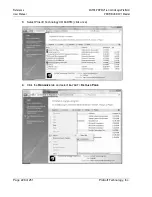
Страница 228: ...MVI56 PDPMV1 ControlLogix Platform User Manual PROFIBUS DPV1 Master Page 228 of 251 ProSoft Technology Inc 3 Select Prosoft Technology COM DTM click once 4 Click the ORGANIZE tab and select LAYOUT DET...

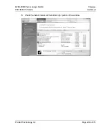
Страница 229: ...MVI56 PDPMV1 ControlLogix Platform Reference PROFIBUS DPV1 Master User Manual Page 229 of 251 ProSoft Technology Inc 5 Check the Install Version at the bottom right portion of the window...

Страница 230: ...MVI56 PDPMV1 module These two data blocks Input Data and Output Data consist of a data structure that provides for the movement of Input Data image from PROFIBUS slave devices Output Data image for wr...

Страница 231: ...us Block containing status data refer to Status Objects 1 to 4 Input Data Input data from PROFIBUS network with each block containing up to 200 words of data refer to Input Data Block 1 to 4 Output Da...

Страница 232: ...block is a function of the PROFIBUS network configuration Block ID 1 Slave bytes 0 to 399 Block ID 2 Slave bytes 400 to 799 Block ID 3 Slave bytes 800 to 1199 Block ID 4 Slave bytes 1200 to 1535 200...

Страница 233: ...of PROFIBUS input data to transfer from the PROFIBUS Master to the processor within the Input Data blocks Value is selected during user configuration 14 15 PROFIBUS Output Data size The number of word...

Страница 234: ...active state for the first time the associated bit is set This bit is then cleared when the slave enters Data Exchange state If a slave indicates Extended Diagnostics when it is in Data Exchange state...

Страница 235: ...ounter MVI56 PDPMV1 module program scan counter Can be used to gauge application code scan time performance 96 97 Module PROFIBUS output image data update counter Counter representing the number of ti...

Страница 236: ...inated 120 145 Reserved Reserved for future use 146 147 In mailbox queue count Number of message in the in mailbox queue 148 149 Out mailbox queue count Number of message in the out mailbox queue 150...

Страница 237: ...number 1 to 4 1 200 PROFIBUS Output Data PROFIBUS Output Data Data going to the PROFIBUS Network 201 201 Reserved Reserved for future use 202 202 Reserved Reserved for future use 203 203 Reserved Rese...

Страница 238: ...PROFIBUS input data fits into one input backplane block It allows the switching between two blocks with different block IDs but with same content So in fact block 0 and block 1 will transfer the same...

Страница 239: ...et Start End Name Description 0 0 Block Write ID Block ID of the next write block It will contain a value of 9990 because the module expects the next block from the processor to have the same block ID...

Страница 240: ...k MVI56PDPMV1 Util OutputWordsInLastWriteBlock Number of PROFIBUS output data words in the last write block The last write block is the one with highest block ID 11 11 Read Block ID 9990 Input Data Bl...

Страница 241: ...transfer from the PROFIBUS Master to the processor within the Input Data blocks Value is selected during user configuration 14 15 PROFIBUS Output Data size The number of words to transfer from the pr...

Страница 242: ...active state for the first time the associated bit is set This bit is then cleared when the slave enters Data Exchange state If a slave indicates Extended Diagnostics when it is in Data Exchange state...

Страница 243: ...le program scan counter Can be used to gauge application code scan time performance 96 97 Module PROFIBUS output image data update counter Counter representing the number of times the output data imag...

Страница 244: ...lbox control index 156 157 Current alarm control index Current alarm control index 158 496 Reserved for future use 496 497 Index of Output image to receive 1 to 4 for data 0 or 1 if no data 498 499 Bl...

Страница 245: ...ction The only two service types supported by the module are Get Attribute Single 0x0E and Set Attribute Single 0x10 The Class parameter must always be set to a value of 4 The instance value selects t...

Страница 246: ...MVI56 PDPMV1 ControlLogix Platform User Manual PROFIBUS DPV1 Master Page 246 of 251 ProSoft Technology Inc...

Страница 247: ...plant down issues North America Corporate Location Europe Middle East Africa Regional Office Phone 1 661 716 5100 info prosoft technology com Languages spoken English Spanish REGIONAL TECH SUPPORT sup...

Страница 248: ...Support Service Warranty MVI56 PDPMV1 ControlLogix Platform User Manual PROFIBUS DPV1 Master Page 248 of 251 ProSoft Technology Inc...

Страница 249: ...17 Connecting Your PC to the Module 78 Constructing a Bus Cable for PROFIBUS DP 203 Contacting Technical Support 247 COP Instruction input 42 COP Instruction output 43 Creating a New RSLogix5000 Proje...

Страница 250: ...Stop Slave 168 Mailbox Message Commands 147 Mailbox Message Queuing 130 Mailbox Messaging 129 194 Mailbox Messaging Error Codes 151 153 155 170 Main Menu 187 Markings 3 Master Slave Communication Pha...

Страница 251: ...PCB for Diagnostics 181 Using The Autoscan Feature 89 Using the CIPconnect Path Editor 219 222 Using the Diagnostic Window in ProSoft Configuration Builder 184 Using the MVI56 PDPMV1 Add On Instructi...

Отзывы: