


Programming the Outputs
Page 65 of 102
Note2:
When an output is disabled and then re-
enabled, the control is reset and all user control
settings removed. This action puts the relay control
into a defined state prior to reconfiguring.
A sensor input can be used as an analyzer or
monitor, but to be able to control a feeder or a valve,
it needs to be linked to an output. Linking is
achieved in the configuration process. See Section
10.6 Configuring a feed relay
10.1 Frequency/Pulse Outputs:
Frequency controlled Pumps feed chemicals at
varying rates (Frequency controlled pumps are
outputs 6 to 9)
Any analog sensor: temperature, flow, corrosion
rate, ORP… may be used to frequency control a
pulse controlled pump. The output is proportional to
the input sensor using part or all of the sensor
range.
Example: Using a pH sensor with an input of 0 to
14pH, you could set 0 pulses at 14pH and maximum
pulses at 0pH. The higher the pH, the slower the
output pulses.
Or you could set the output as a range of 0 pulses at
7.2pH and maximum pulses at 7.8pH. This
shortened range would cause the pump to speed up
and down more rapidly with changes in pH and is in
the opposite direction as you might use on an acid
pump.
Pump speed control is achieved without using a 4-
20mA pump.
Alarm settings for Volume @Max SPM (Strokes per
Minute) and Volume/Day are limited to 500 Gallons.
These alarms are adjustable in the output alarm
menu.
The alarm for volume @ maximum strokes per
minute was created for the situation where a pump
is at full speed for too long a period of time. For
example, an acid pump that cannot lower the pH
enough to slow the pump from the maximum speed
after say 10 minutes, might be considered an alarm
condition. Waiting until the pump feeds more than
the volume per day would be much too long.
If you calculate the pump is feeding, for example, 24
GPD at 100% speed, you know that setting the
Volume @ max stroke will alarm in one hour if set
for 1 gallon. (24GPD / 24 hours = 1 GPH).
So if you want the pump to alarm after 10 minutes,
enter 1/6
th
of a gallon, or 0.1667G and if the pump
runs at 100% for 10 minutes, it will have pumped
01.667 gallons and trip the alarm.
The Four OptoMOS DOs(Digital/Frequency Outputs)
P6,P7,P8, & P9 can each be set to either:
1- Pulse
output/Frequency
2- ON/OFF
Note:
this setup is done during the enabling of the
output.
Output relays, once configured, must be disabled
and re-enabled if you need to change their type. See
section
10.3
Enable and Configure a Relay
.
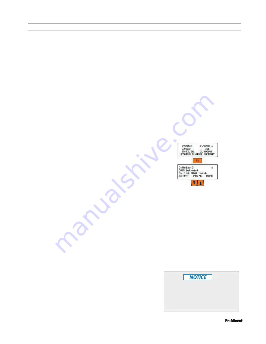
10.2 Determine if a Relay is Enabled:
1- From the Home display, press the
F1
STATUS
key.
2- Scroll through the enabled I/O. If you
do not
see
your relay, it is disabled.
10.3 Enable and Configure a Relay
1- Press
the
MENU
key
2- Use the ARROW keys to scroll to System
then press
OK
.
1-
2-
3- Scroll up to Enable I/O then press
OK
4- Scroll through the disabled I/Os until you
see your relay.
5- Once the output is selected, press
F3
ENABLE key.
To complete the
enable
process, you must
choose a relay type.
This naming/Descriptor procedure is
the same for all I/O points; Inputs and
Outputs, digital and analog and that
also includes 4-20mA ports.
Содержание Aegis-II
Страница 26: ...Mounting and Installation Page 26 of 102 Figure 14 Aegis II overall location of major components ...
Страница 27: ...Mounting and Installation Page 27 of 102 Figure 15 Aegis II motherboard general arrangement ...
Страница 28: ...Mounting and Installation Page 28 of 102 Figure 16 Main PC board Input Wiring diagram ...