


Mounting and Installation
Page 34 of 102
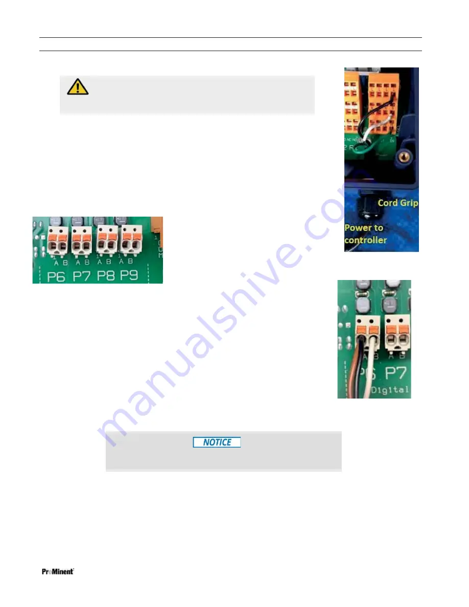
Figure 29 Digital DC (Pulse) outputs 6-9
Poor electrical connection may cause incorrect measurements. Once a
wire is terminated, tug gently on the wire to ensure it is not loose.
CAUTION!
All electrical wiring shall be performed by a licensed electrician,
in accordance with local and national electric codes.
6.3.5.7 Connecting a Power Cord
Remove a knock-out from the bottom of the controller and install the cord using a NEMA4/IP66
cord grip as shown in figure 28. See also Figures 9 and 10.
Terminate the line, neutral and ground wires as shown in figure 28. See also figure 22 in the
overview section to open the terminations.
6.3.6 Frequency
Output
Termination
Outputs 6 through 9 are unpowered digital outputs rated for 24VDC / 250mA which can be
configured as a Pulse or ON/OFF output. See Figure 29.
In pulse mode, these outputs can control the speed of
pulse driven pumps. The frequency outputs vary the
pump speed in much the same manner as a 4-20mA
signal.
Figure 28 Power cord
In the ON/OFF mode, the outputs will start or stop a pump. The pump frequency
will then be determined manually at the pump.
6.3.6.1 Using a Universal Control Cable on a Pulse Output Relay
Prominent pumps using the Universal Control cable will terminate using the brown, black and
white wires as shown in Figure 30. This connection is not polarity sensitive. The black is
common. The white is the pulse signal. The brown wire is for pause/enable. When the brown is
not shorted to the black wire, the pump will be in pause mode.
Figure 30 Universal Control
Cable on Output Relay P6
6.3.7 Wiring sensors to the controller
Signal inputs to the controller attach to the main printed circuit board (PCB) or to expansion driver cards. Each input signal is
assigned a letter, A through Z, for program identification. Analog outputs (4-20mA) are assigned an ID of C1 through C8.
Digital outputs are assigned numbers 1 through 9.
In this way, outputs may be programmed to operate based on the status of specified inputs. Relay 3, for example, might be
energized when sensor E reaches a programmed setpoint. Analog outputs (4-20mA) can be programmed to vary
proportionally to an analog input in a forward or reverse direction. Refer to the Aegis Browser manual for programming detail.
6.3.7.1 Inputs on the Main Board
Содержание Aegis-II
Страница 26: ...Mounting and Installation Page 26 of 102 Figure 14 Aegis II overall location of major components ...
Страница 27: ...Mounting and Installation Page 27 of 102 Figure 15 Aegis II motherboard general arrangement ...
Страница 28: ...Mounting and Installation Page 28 of 102 Figure 16 Main PC board Input Wiring diagram ...