


Programming the Outputs
Page 64 of 102
9.11.4 Changing or Unlinking a Digital Input
Tied to a 4-20mA Output
If a digital input is used as an interlock for a
relay, it must be unlinked prior to being
disabled.
1- Press
MENU
2- Scroll down to I/O Setup and Press
OK
3- Scroll down to the 4-20mA Output where the
interlock is being used. Press
OK
.
4- Press
F2
Next two times to get to the Interlocks
5- Press
F1
(Remove) to unlink the digital input
from this output.
6- Choose a new interlock or press
OK
to save
the change. If more than one interlock, use the
arrows to see them and remove as needed.
ESC
, Escape will void all changes.
See also
10.8 Interlocks
Return to
9.11 to Disable an Analog or Digital
Input
.
9.12 Phantom Inputs
The Aegis has a maximum of 10 analog inputs, A
through J. Analog inputs are linked to the first 14
letter of the alphabet, A through N, which means 4
letters, K through N cannot be assigned to any wired
input. They have no terminals. These are phantom
or virtual analog inputs.
Digital Inputs are lettered from O to Z. Wired inputs
are labeled from O to V. Input designators W, X, Y
and Z can be used as phantom digital inputs.
In some cases it is advantageous to create a
phantom sensor to duplicate an existing hardware
sensor. Another use is to assign a
phantom “
virtual
”
input to show and data log a temperature sensor or
flow switch that is an integral part of another sensor.
We use the common CTFs sensor as an example to
highlight how this is done. See 9.1.2 Enable a CTFS
Any analog input, including
Phantom’s, can be used
as a manual input to data log operator test data. If
you test the water each turn, you can log that value
into this controller. It will be time stamped and is part
of the complete historical database with all sensors,
phantoms and relays.
Analog phantoms can be programmed to be used in
control outputs in the same manner as any sensor
input.
10 Programming the Control Outputs
(Relay and 4-20mA)
This section will describe how to configure relays to
control a process and 4-20mA outputs for control or
as an indication of an analog input sensor. Outputs
can be based on a sensor with ON/OFF set-points, a
timed event, a combination of an event and a
sensor, base feed, percent timer, bleed and then
feed and more options. These can include
interlocking with digital inputs, blocks from other
relays and a few special controls. Special Controls
include the boiler captured sample routine, variable
cycles, timed cycling, time modulation and PID.
The part number and identification code on the order
placed with ProMinent will determine the sensors
and outputs that were configured as default at the
factory. Some sensors may have been pre-wired,
(pH and ORP coaxial cables, some conductivity and
temperature sensors, ppm residual sensors). Other
sensors like water meters and chemical feeders may
have been configured, but will have to be field
installed, wired, enabled and possibly re-configured
during commissioning.
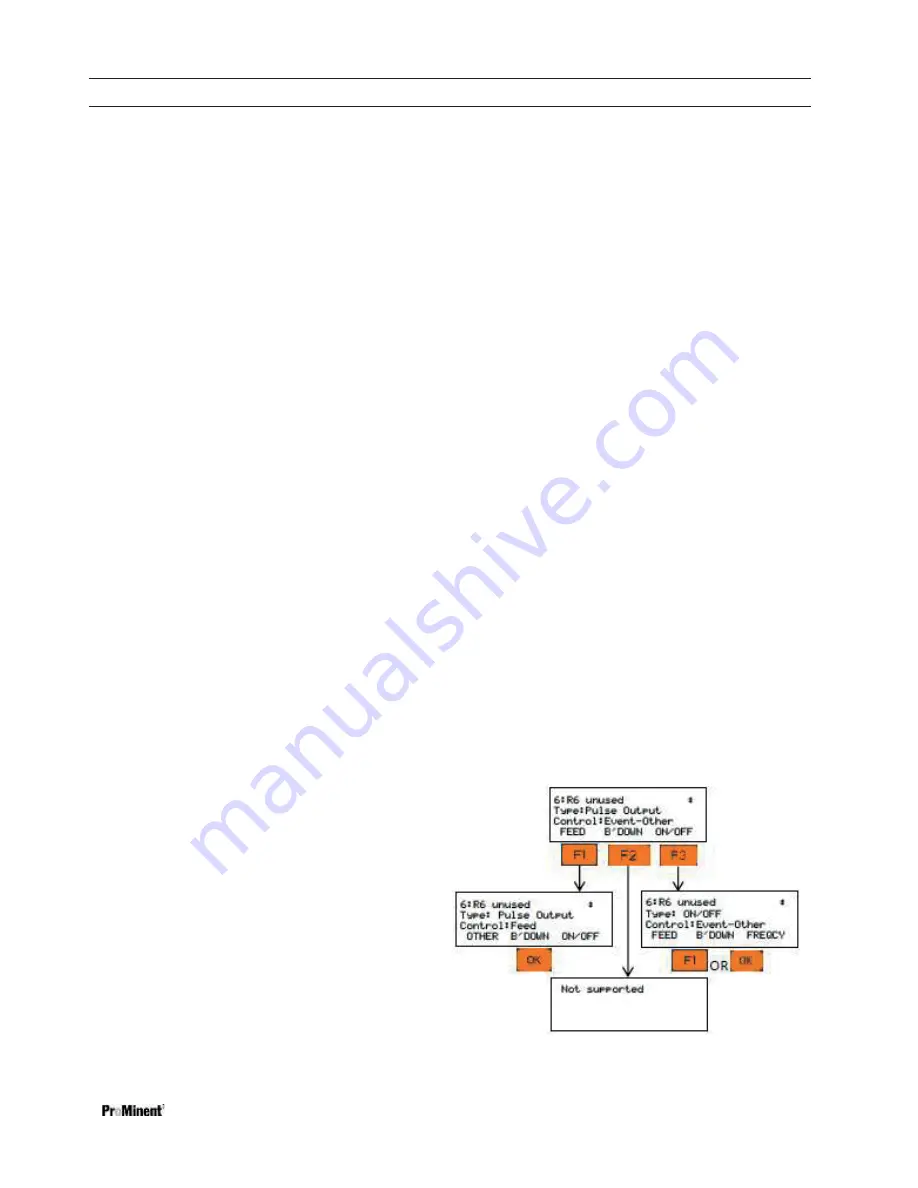
Note1:
Relays can be enabled as one of three
types; Blowdown, Events-Other or Feed. Once a
relay is enabled, the only way to change the
assignment from one to another is to disable the
relay and enable it as a different usage.
The
B’DOWN (
Blowdown) choice means that the
relay must be linked to a conductivity sensor, which
can include a 4-20mA input from our toroidal probe.
The output will turn on and off based on set-points.
The Events-Other and Feed choices require further
programming as well. These steps are explained in
detail later.
Содержание Aegis-II
Страница 26: ...Mounting and Installation Page 26 of 102 Figure 14 Aegis II overall location of major components ...
Страница 27: ...Mounting and Installation Page 27 of 102 Figure 15 Aegis II motherboard general arrangement ...
Страница 28: ...Mounting and Installation Page 28 of 102 Figure 16 Main PC board Input Wiring diagram ...