


Chapter 3 Connections and Wiring
ADSD-S-S
17
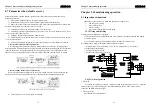
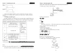
2) The cables connected to R, S, T and U, V, W terminals should be placed in separate conduits from
the encoder or other signal cables. Separate them as far as possible more than 30 cm interval.
3) If the encoder cable is need to lengthen, please use a twisted-shield signal wire with grounding
conductor. The wire length should be 20m or less. For lengths greater than 20m, the wire gauge
should be doubled in order to lessen any signal attenuation.
3-1-3 Using wire specifications
Connect terminal
Servo drive model and cables
specifications
Connect
terminal
Label
Connector
description
(
15S
)
(
20S
)
(
30S
)
L1
、
L2
Control
power
terminal
1mm
2
AWG18
1mm
2
AWG18
1mm
2
AWG18
R,S,T
Main power
terminal
1mm
2
AWG18
1mm
2
AWG18
1.5mm
2
AWG16
U,V,W
Motor power
terminal
1mm
2
AWG18
1mm
2
AWG18
1.5mm
2
AWG16
Terminal
block
(
TB
)
PE
Ground
terminal
1mm
2
AWG18
1mm
2
AWG18
1.5mm
2
AWG16
CN1
Connector
1~26 pin
Control
instruction
interface
0.2mm² shielded twisted-pair
cables
CN2
Connector
1~15 pin
Encoder
interface
0.2mm² shielded twisted-pair
cables
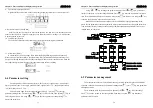
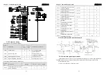
3-1-4 Power supply connections for control circuit
Servo drives wiring connections include single phase connection and three phase connection.
Single phase connection can only fit for 1KW following models. In below drawing, 1MC/x is
electromagnetic contactor coil, 1MC/ a is self-holding power, 1MC is main circuit interface.
Three-phase power supply connection method
(
fit for unit whose module power crest value
1KW
or above
)
.
Chapter 3 Connections and Wiring
ADSD-S-S
18
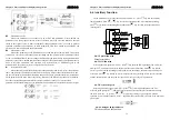
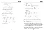
Single-phase power supply connection method
(
fit for unit whose module power crest value is
under 1KW
)
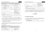
3-2 CN1 Input / Output Interface
CN1 I/O Interface
signal d
escription (
Illustration shows arrangement of the
p
lug welding feet)
1
10
19


