


Chapter 5 Commissioning operation
ADSD-S-S
49
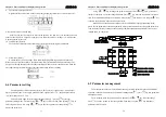
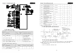
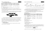
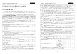
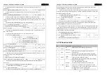
5-2-9 The position control the gain
paramet
ers
designation
range
default
value
unit
apply
L009
position loop gain
1
~
1000
40
1/s
P
L021
Position loop
feed forward
gain
0
~
100
0
%
P
L022
Position loop feed forward
filtering time constant
0.20
~
50.00
1.00
ms
P
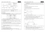
Because the position loop including speed loop, in accordance with the outer after inner ring
order, first set up load than inertia, then adjust speed loop gain and speed loop integral time constant,
finally change position loop gain.
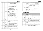
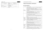
The following is the position
controller
system,
i
ncreases the
position loop gain K
can improve
the position loop bandwidth, but being limited by the speed loop bandwidth. So want to increase the
position loop gain that must
improve the speed loop bandwidth at the first.
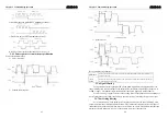
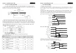
differential
L021
L022
position loop gain (
Kp)
+speed
instruction
position
instruction
+
-
position
feedback
+
F
eed forward
can reduce the position loop control phase lag, can reduce the position control
position tracking error and the less time of the orientation. F
eed forward
volume increasing and the
position control the tracking error decreasing, but too big would make the system unstable and
overshoot. If the electronic gear ratios are greater than 10 also easy to
produce
noise. Application
can set the L021as 0%,when need high response and low tracking error, can appropriately increased
and not more than 80%, also need to adjust the position loop f
eed forward
filtering time
constant(parameters L022).
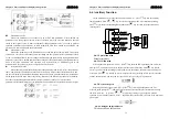
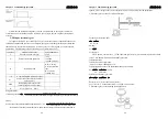
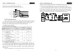
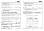
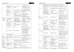
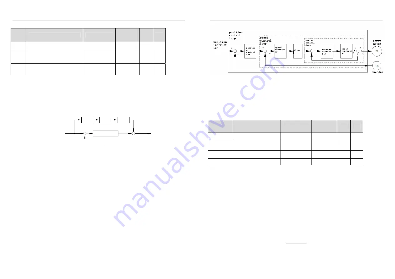
5-2-10 Gain adjustment
Drive including current control ring, speed control loop and the position control ring three
control circuit, follow the control diagram:
Chapter 5 Commissioning operation
ADSD-S-S
50
In the abstract, the inner control circuit of the bandwidth must be higher than the outer layer,
otherwise the whole control system would not be stable that may cause vibration or response not
better, so the three control loop bandwidth relationship as follows:
Current loop bandwidth>Speed loop bandwidth>Position loop bandwidth.
Since drive has been adjusted for the current control loop well, so that users simply adjust
speed control loop and the position control ring parameters
.
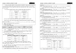
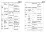
1.
Gain parameters
Gain relevant parameters:
parameters
designation
range
default
value
unit apply
L005
Speed loop gain
1
~
3000
40
Hz
P
L006
Speed loop integral time
constant
1.0
~
1000.0
20.0
ms P
L009
position loop gain
1
~
1000
40
1/s
P
L017
Load than inertia
0.0
~
200.0
1.5
倍
P
Symbols defined as follows:
K
V
: Speed loop gain;
T
i
: Speed loop integral time constant;
K
p
: P
osition loop gain;
G: Load inertia ratio
(
L017);
J
L
: Inertia converts to the motor shaft load;
J
M
: Motor rotor rotating inertia.
1).Speed loop gain K
V
Speed loop gain K
V
directly
decide
the response of the speed loop bandwidth .In the premise
that the mechanical systems do not produce vibration or noise, increasing velocity gain value, the
speed response can accelerate faster, the peed command following is the better. But too big set was
easy to cause mechanical resonance. Speed loop bandwidth shows as:
)
(
*
/
1
1
z
bandwidth
loop
speed
the
Hz
K
J
J
G
H
V
M
L
+
+
=
)
(
If the load inertia ratio is right, so that speed loop bandwidth equals speed loop gain K
V .


