


Chapter 6 Parameter function description
ADSD-S-S
59
4
:
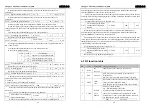
When doing the keyboard adjustment (Sr) operation, need to set keyboard speed command.
5
:
When doing the demonstrate speed command need to set the demonstrate speed command and
speed instructions will change automatically .
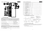
L029
instructions pulse electronic gear
molecules 1
1
~
32767
1 - P
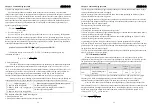
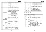
For input pulse step or times frequency can match with all kinds of pulse source easily, in
order to achieve the pulse resolution that user need.
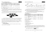
Instructions pulse electronic gear molecules N is decided by DI input GEAR1, GEAR2. The
common denominator M is set by L030 parameters.
DI signal(note)
GEAR2 GEAR1
instructions pulse electronic
gear molecules N
0 0
Molecular
1(L029)
0 1
Molecular
2(L031)
1 0
Molecular
3(L032)
1 1
Molecular
4(L033)
Note
:
0 means OFF, 1 means ON.
Input pulse instructions get the position instructions after the N/M change, ratio value range :
1/50<N/M<200
L030
Instructions pulse electronic gear
denominator
1
~
32767
1 - P
Instructions pulse electronic gear denominator M
,
application method reference parameters
L029 instructions.
L031
instructions pulse electronic gear
molecules 2
1
~
32767
1 - P
Reference explanation of the L029 parameters.
L032
instructions pulse electronic gear
molecules 3
1
~
32767
1 - P
Reference explanation of the L029 parameters.
L033 instructions pulse electronic gear
1
~
32767
1 - P
Chapter 6 Parameter function description
ADSD-S-S
60
molecules 4
Reference explanation of the L029 parameters.
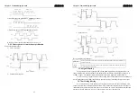
pulse + symbol
0
positive/reverse
pulse
1
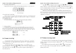
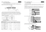
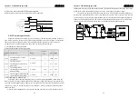
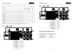
L035 Instructions pulse input methods
quadrate pulse
2
0 - P
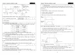
Setting instruction input pulses mode
0:Pulse + symbol(L035 parameters set as 0)
1: positive/reverse pulse(L035 parameters set as 1)
2: Quadrate pulse(L035 parameters set as 2)
Note: The arrows represent the count, and L036 = 0, L037 = 0.
Command input pulse diagram:


