


Chapter 7 Alarm
ADSD-S-S
71
Chapter7 Alarm
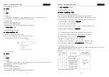
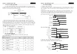
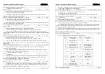
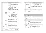
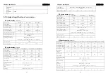
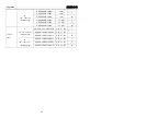
7-1 Alarm messages table
alarm
code
alarm name
alarm content
alarm
clear
Err--
no alarm
operating
normally
-
Err 1
over speed
motor speed over than the largest limit
N
Err 2
main circuit
over-voltage
The main power voltage more than
rating value
N
Err 4
position over
deviation
numerical value of position deviation
over the setting value
Y
Err 7
Abnormal driving ban
both CCWL and CWL driving ban
import invalid
N
Err 8
position deviation
counter overflow
the absolute value of the position
deviation counter more than 230
Y
Err 9
encoder signal fault
encoder signal loss
N
Err11
power module fault
power module occurs fault
N
Err12
over-current
motor current is too large
N
Err13
overload
the motor over load
N
Err14
braking peak power
overload
brake short time transient load is too
large
N
Err15
encoder counting
errors
encoder counting
abnormal
N
Err16
motor overheat
motor over heat exceeds the setting
value.(I2t checking)
N
Err17
braking average
power overload
braking long time, average load too
heavy
N
Err18
power module
overload
power module average load output too
big
N
Err20
EEPROM error
EEPROM reading and writing mistake
N
Err21
logic circuit error
the processor peripheral logic circuit
fault
N
Err23
AD conversion errors
circuit or current sensor mistakes
N
Err24
lower voltage control
control circuit LDO fault
N
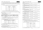
Chapter 7 Alarm
ADSD-S-S
72
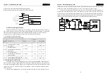
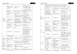
Err29
torque overload alarm
motor load more than numerical and
duration were set by users
N
Err30
encoder Z signal
losing
encoder Z signal cannot appear
N
Err31
encoder UVW signal
error
Encoder UVW signal error
or extreme number does not match
N
Err32
encoder UVW signal
illegal code
UVW signal presents all high or low
level
N
Err33
province line encoder
signal error
power timing without high impedance
N
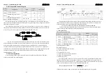
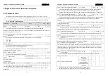
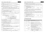
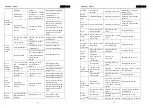
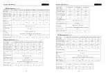
7-2 Causes and treatment of the alarm
alarm
code
reason
inspection
treatment
motor wiring U, V,
W sequence
mistakes
Checking U,V,W
wiring
Connecting to U, V, W
wiring properly, and
corresponding drives plug
the U, V, W tag.
motor speed
overshoot
checking the working
condition and the
parameters
adjust the servo gain,
make it reducing
overshoot; under the speed
control, can increase and
deceleration time
Err 1
over speed
encoder wiring
error
checking the encoder
wiring
wiring properly
input ac power is
too high
checking the power
voltage
make voltage accord with
specifications of product
regenerative
braking fault
regenerative braking
resistance or brake
tube is invalid or not
the wiring disconnect
Please contact with
distributors or
manufacturer to solve.
Err 2
main circuit
over-voltage
regenerative
braking energy is
too big
checking the brake
load rate
Reducing the frequency of
the
start-stop, i
ncreasing
speed-up and speed-down
time, reducing torque limit
and the load inertia,
replacement of the more
high-power drives and
motors.


