


Chapter 6 Parameter function description
ADSD-S-S
65
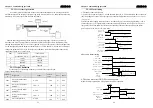
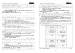
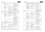
Forward drive banned (CCWL) and reversal drive ban(CWL) is used to hold on stroke limits,
and using closed contacts, when the input is ON the motor can run to the direction, if it is OFF, it
can’t. If is not used to hold on stroke limits, ignored by this parameter that can work without linking
drive ban signal.
The parameter default is ignored, if need to use, that must change the parameters.
No.
Reversal
drive
ban(CWL)
Forward drive
banned (CCWL)
0
employ employ
1
employ ignore
2
ignore employ
3
ignore ignore
Employ: when the input is ON the motor can run to the direction, if it is OFF, it not.
Ignore: the motor runs to the direction without linking, and the drive ban signal is inaction.
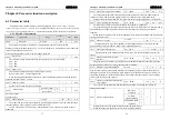
L098 Force enable
0~1
3
-
ALL
0
:
Enable is controlled by the SON input from DI
1
:
Software force enable
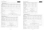
6-1-2 1 Period of parameters
parameters
designation
range
default
value
unit
apply
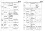
L100
Digital input DI1
function
-21
~
21
1
-
ALL
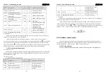
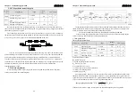
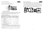
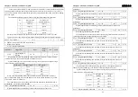
Digital input DI1 function planning, the absolute value parameters means function,
symbol means logic, the function referred to chapter 5.5 please.
Symbol means logic. Positive means positive logical, negative means negative logic
(ON as effective, OFF as invalid)
parameters
DI input signal
DI results
open OFF
positive
close ON
open ON
negative
close OFF
When many input channel choose the same function, the results of the function is
logic or relationship. Such as both L100 and L101 are set as 1(SON function), any of DI1
or DI2 is ON the SON is effective.
The input function is not selected by the L100-L104 parameters, that the function is
not planning, the results is OFF (invalid).
L101
Digital input DI2 function
-21
~
21
2
-
ALL
Digital input DI2 function planning, reference the description of the L100
Chapter 6 Parameter function description
ADSD-S-S
66
parameters.
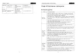
L102
Digital input DI3 function
-21
~
21
3
-
ALL
Digital input DI3 function planning, reference the description of the L100
parameters.
L103
Digital input DI4 function
-21
~
21
4
-
ALL
Digital input DI4 function planning, reference the description of the L100
parameters.
L104
Digital input DI5 function
-21
~
21
20
-
ALL
Digital input DI5 function planning, reference the description of the L100
parameters.
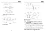
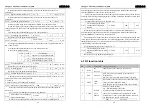
L110
Digital input DI1 filter
0.1
~
100.0
2.0
ms ALL
DI1 input digital filtering time constant
The smaller numerical, the faster speed response, the greater numerical, the slower
speed response but the stronger filtering out noise ability
L111
Digital input DI2 filter
0.1
~
100.0
2.0
ms ALL
DI2 input digital filtering time constant, reference the description of the
L110 parameters.
。
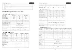
L112
Digital input DI3 filter
0.1
~
100.0
2.0
ms ALL
DI3 input digital filtering time constant, reference the description of the L110
parameters.
L113
Digital input DI4 filter
0.1
~
100.0
2.0
ms ALL
DI4 input digital filtering time constant, reference the description of the L110
parameters.
。
L114
Digital input DI5 filter
0.1
~
100.0
2.0
ms ALL
DI5 input digital filtering time constant, reference the description of the L110
parameters.
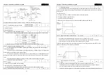
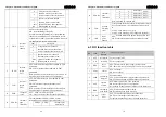
L130
Digital output DO1 function
-12
~
12
2
-
ALL
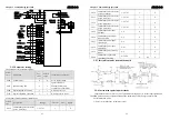
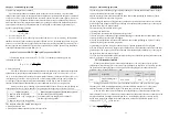
Digital output DO1 function planning, the absolute value parameters means
function, symbol means logic, the function referred to chapter 6-3 please.
Symbol means logic. Positive means positive logical, negative means negative logic
(ON as effective, OFF as invalid)
parameters
Corresponding
function
DO output
signal
ON close
positive
OFF
open
ON
close
negative
OFF open
L131 Digital output DO2 function
-12
~
12
3
-
ALL


