


Chapter 3 Connections and Wiring
ADSD-S-S
25
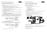
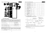
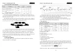
3-4-6 Input / output digital signal interface definition
Digital Signal input interface definition .
Each digital signal input interface is programmable, through the corresponding parameters
can be set at different function. The default value of factory definition as follows, users can
according to what they need to modify.
parameters code
range
default
value
unit
apply
L100
Digital input DI1 function
-21
~
21
1
-
ALL
L101
Digital input DI2 function
-21
~
21
2
-
ALL
L102
Digital input DI3 function
-21
~
21
3
-
ALL
L103
Digital input DI4 function
-21
~
21
4
-
ALL
L104
Digital input DI5 function
-21
~
21
20
-
ALL
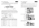
Absolute value of parameters means function, symbol means logic. Positive means positive
logical, negative means negative logic (ON as effective, OFF as invalid):
Parameters
DI input signal
DI results
open OFF
Positive
close
ON
open ON
Negative
close
OFF
DI function description table:
code
symbol
function
0 NULL
invalid
1 SON
Servo
on
2 ARST
Alarm
clear
3 CCWL
Positive drive banned
4 CWL
Negative drive banned
5 TCCW
Positive torque limit
6 TCW
Negative torque limit
15 EMG
Emergency
stop
18
GEAR1 Electronic gear selection 1
19
GEAR2 Electronic gear selection 2
20
CLR
Position deviation clear
21
INH
Input pulse banned
Digital output interface definition
Each digital signal output interface is programmable, through the corresponding
parameters can be set at different function. The default value of factory definition as follows, users
can according to what they need to modify.
Chapter 3 Connections and Wiring
ADSD-S-S
26
parameters code
range
default
value
unit
apply
L130
Digital output
DO1function
-11
~
11
2
-
ALL
L131
Digital output
DO2function
-11
~
11
3
-
ALL
L132
Digital output
DO3function
-11
~
11
8
-
ALL
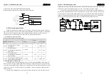
Absolute value of parameters means function, symbol means logic.0 forced to OFF, 1 forced
to ON. Positive means positive logical, negative means negative logic.
Parameter values
DO input
digital
DO results
conduction
ON
positive
open
OFF
conduction
ON
negative
open
OFF
DO function description table
NO.
code
DO function
0 OFF
Always off
1 ON
Always on
2 RDY
Servo ready
3 ALM
Alarm
5 COIN Positioning complete
6 ASP
Speed to arrived
8 BRK Electromagnetic brake
11 TRQL
Torque restrictions


