


User Manual
E727T0005, valid for E-727
BRO, 2019-06-28
Physik Instrumente (PI) GmbH & Co. KG, Auf der Roemerstrasse 1, 76228 Karlsruhe, Germany
Page 115 / 240
Phone +49 721 4846-0, Fax +49 721 4846-1019, Email
In addition, for linear bi-directional scanning applications, the tracking error is not a constant, as
with other types of linear PID servo systems, but changes with the scan position. This is caused by
the non-linearity of piezo actuators and the servo-controller's limited dynamic performance. As a
result of these factors, the scan position is not exactly proportional to time but exhibits dynamic
non-linearity.
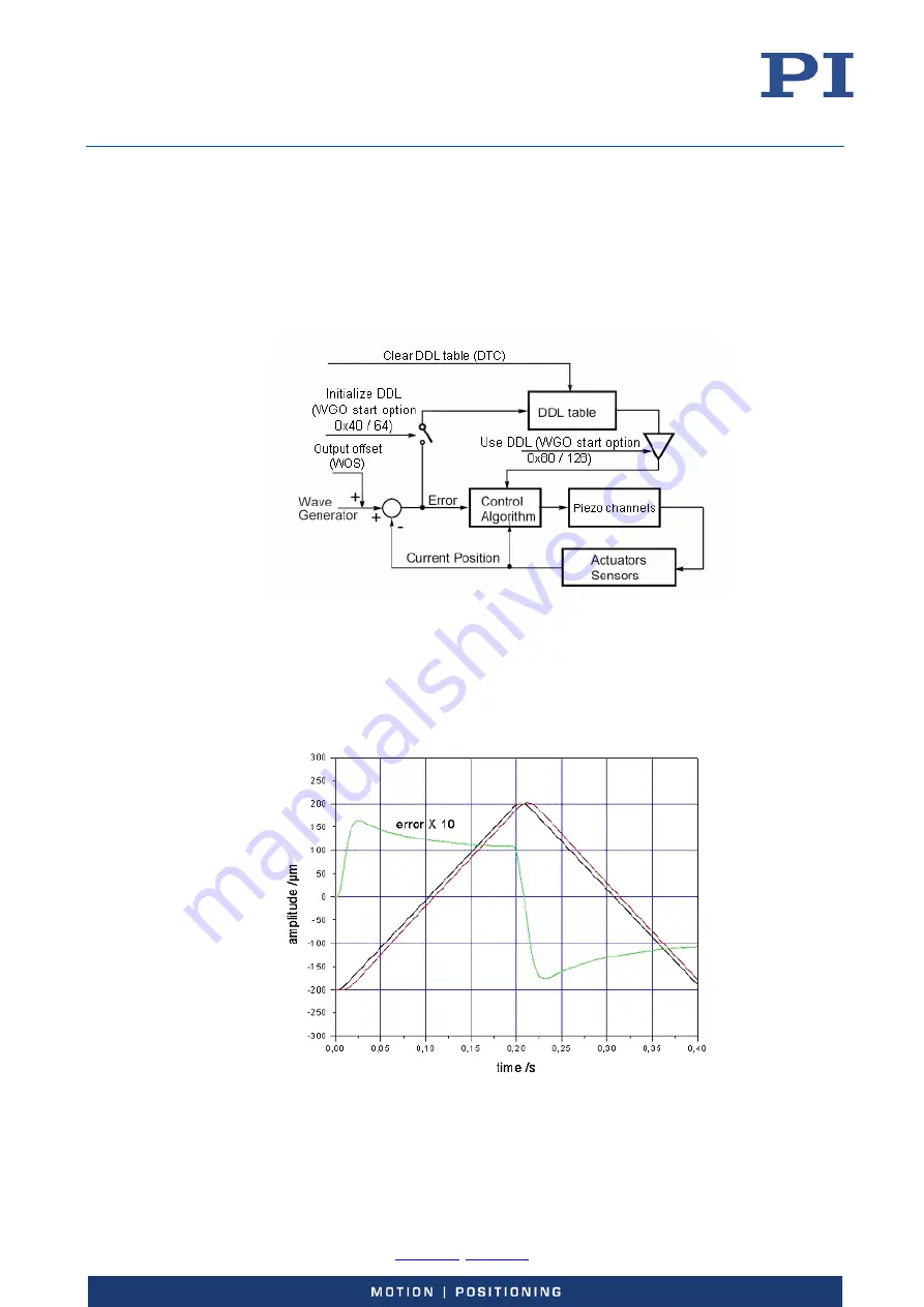
For periodic motion it is possible to record the errors for an axis during one or more DDL
initialization periods and then compensate for them in all subsequent periods. The principle of DDL
is thus the inclusion of an error compensation in addition to the servo-control loop.
Figure 33: DDL block diagram, for one axis
Example:
A simple 400 µm forward and backward scan at 2.5 Hz. Even though the frequency is not high,
there is still a static error of about ±10 µm and a dynamic error of about ±5 µm. The dynamic error
indicates that the scan speed is not constant. This error will deteriorate the scanning accuracy.
Figure 34: Without DDL