20
Allocating a decoder
Some TV channels send coded TV signals that can only be viewed
properly with a purchased or rented decoder. You can connect such a
decoder (descrambler) to your DVD recorder. The following function
automatically activates the connected decoder for the TV channel you
want to watch.
If your TV set supports 'Easy Link' the decoder must be assigned to the
relevant TV channel on the TV set (see the operating instructions for your TV
set). Settings cannot then be made in this menu.
Preparation:
•) Switch on the TV set, and if necessary, select the programme
number for the DVD recorder.
•) Switch on the DVD recorder.
1
Use the
CHANNEL
q
and
CHANNEL
r
buttons or the
number buttons
0..9
on the remote control to select the TV
channel for which you want to use the decoder.
O
If necessary, use the
MONITOR
button to switch to the
internal tuner.
2
Press the
SYSTEM MENU
button on the remote control.
P
The menu bar appears.
3
Select '
A
' symbol with
D
or
C
.
4
Select '
Installation
' using
B
or
A
and confirm with
C
.
5
Select '
Manual search
' using
B
or
A
and confirm with
C
.
Installation
Manual search
Channel/freq.
CH
Entry/search
01
Programme number
01
TV channel name
BBC1
Decoder
Off
TV system
PAL-BG
NICAM
On
Fine tuning
0
To store
Press OK
6
Select '
Decoder
' using
B
or
A
.
7
Select '
On
' with
C
.
O
To switch off the decoder use
C
to select '
Off
' (Decoder
switched off).
8
Confirm with
OK
.
9
To end, press
SYSTEM MENU
.
Your decoder has now been allocated to this TV channel.
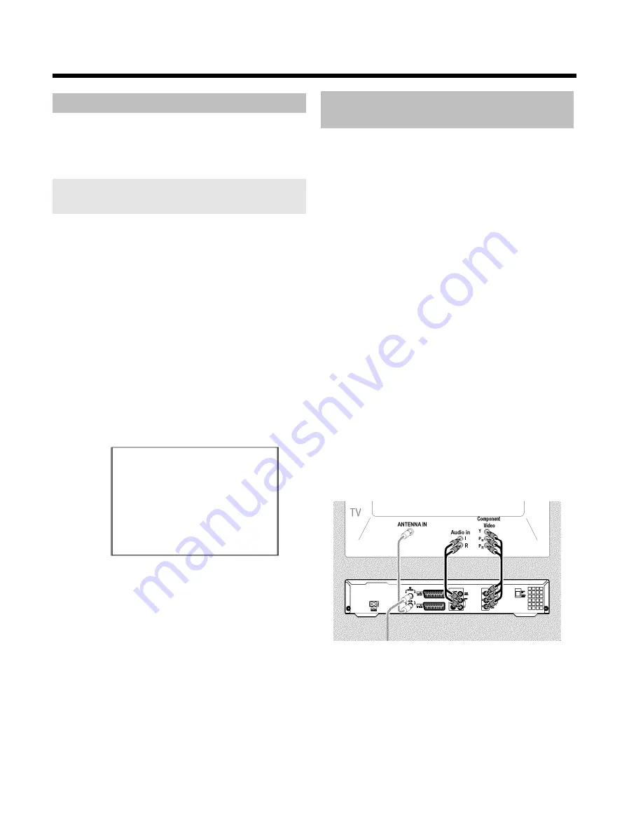
Connection using a component video
(Y Pb Pr/YUV) cable
Component video (Y Pb Pr) is the highest quality picture transmission
option. This is achieved by dividing the video signal into a luminance
signal (Y) and two colour difference signals - red minus luminance (V)
and blue minus luminance (U). As a rule, "Cr, Pr" or "R-Y" is used to
describe the red difference signal and "Cb, Pb" or "B-Y" the blue
difference signal.
These signals are transmitted through separate lines. The connectors of
this cable and the corresponding sockets are usually green (luminance,
Y), blue (U, Pb, Cb, B-Y), and red (V, Pr, Cr, R-Y).
Attention!
If you choose this type of connection, the DVD recorder must already
be connected and completely installed (initial installation complete).
Switching of the signal to the
COMPONENT VIDEO OUT
sockets is
carried out in a menu that is not yet available during the initial
installation.
1
Press the
SYSTEM MENU
button on the remote control.
P
The menu bar appears.
2
Select '
A
' symbol with
D
or
C
.
3
Select the '
' symbol using
B
or
A
and confirm with
C
.
4
Select the line '
Component video output
' using
B
and confirm
with
C
.
5
Select the setting you need with
SELECT
. Choose
'
Progressive Scan
' only if your TV has Progressive Scan.
6
Confirm with
OK
.
For more information on the other settings, read section 'Picture
settings' ('
Video output
') in chapter 'User preferences'.
7
Use a component video (Y Pb Pr) cable, connect the three cinch
sockets (red, blue, green)
COMPONENT VIDEO OUT
at the
back of the DVD recorder with the corresponding three
component video (progressive scan) input sockets of your TV set,
usually labelled 'Component Video Input', 'YUV Input', 'YPbPr',
'YCbCr' or simply 'YUV'.
Additional installation features
Содержание DVDR730/00
Страница 1: ......
Страница 2: ......
Страница 156: ...74 DEUTSCH ENGLISH 3103 605 22012 4405 000 W w n n N N N w w n n w W N n w N w n N n w N N w w N n n W DVDR 730 00 02 ...


