IntelliTouch
®
Control System User’s Guide
36
4.
Continue to name other auxiliary circuits
(AUX2, AUX3, etc.)
: After selecting the
equipment name you want to use for
AUX 1
, press
the button next to the
AUX 2
and choose a circuit
name. The small arrow indicates which circuit is
selected for naming.
5. Repeat the process to assign the other equipment to
circuits on this screen.
6. When you have finished assigning equipment
circuit names, press the
Save
button.
7. Press the
Exit
button to return to the Main screen.
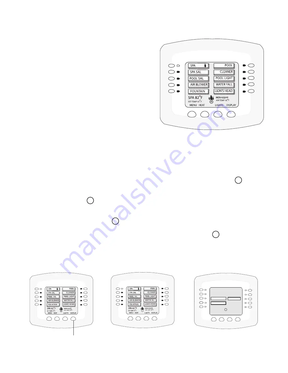
Selecting the Display Screens
There are thee (3) screens to view and setup auxiliary circuits:
•
Main Screen:
Displays assigned auxiliary (AUX 1, AUX 2, etc.) circuit names. An
M
icon
located in the middle lower part of the screen indicates that the “Main Screen” is selected.
•
Display #1
: Displays the auxiliary (AUX 1, AUX 2, etc.) circuits connected to the main Load
Center. The number
1
icon located in the middle lower part of the screen indicates that
circuits for Display #1 is selected.
•
Display #2, #3, or #4
: Displays the auxiliary circuits connected to additional expansion Load
or Power Centers. The number
2
icon located in the middle lower part of the screen indicates
that circuits for Display #2 is selected.
•
Feature:
Displays auxiliary circuits configured as “Feature” circuits. The
F
icon located in
the middle lower part of the screen indicates that Feature circuits screen is selected.
To select the Display screens, press the lower right DISPLAY button to toggle through each of the
screens. For more information, see page 7.
1
MENU
HEAT
LIGHTS
DISPLAY
EDGE PUMP
CLEANERS
F
MON 4:32AM
AIR TEMP 92˚
ALL LIGHTS
WATER FALL
CLEANERS
Main screen
Display #1, #2, #3, or #4 screen
Feature circuits screen
Display button
Содержание INTELLITOUCH
Страница 9: ...vii IntelliTouch Control System User s Guide BlankPage...
Страница 99: ...IntelliTouch Control System User s Guide 89 WORKSHEET FOR SHARED EQUIPMENT SYSTEMS i5 3 i7 3 i9 3 Sheet 1 of 2...
Страница 100: ...IntelliTouch Control System User s Guide 90 WORKSHEET FOR SHARED EQUIPMENT SYSTEMS i5 3 i7 3 i9 3 Sheet 2 of 2...
Страница 101: ...IntelliTouch Control System User s Guide 91 WORKSHEET FOR SINGLE BODY SYSTEMS i5S 3 i9 3S Sheet 1 of 2...
Страница 102: ...IntelliTouch Control System User s Guide 92 WORKSHEET FOR SINGLE BODY SYSTEMS i5S 3 i9 3S Sheet 2 of 2...
Страница 103: ...IntelliTouch Control System User s Guide 93 WORKSHEET FOR DUAL EQUIPMENT SYSTEMS i10 3D Sheet 1 of 2...
Страница 104: ...IntelliTouch Control System User s Guide 94 WORKSHEET FOR DUAL EQUIPMENT SYSTEMS i10 3D Sheet 2 of 2...
Страница 121: ...IntelliTouch Control System User s Guide 111 IntelliTouch Control System Wiring Diagram i10 3D i5 3S i9 3S and i10 3D...
Страница 126: ...NOTES...
Страница 127: ...NOTES SAVE THESE INSTRUCTIONS...


