background image

Reference Guide

013-16123A

Wireless Smart Gate

PS-3225

1

The Swivel Rod Clamp can be detached

*See the PASCO catalog or the PASCO web site www.pasco.com for more information.
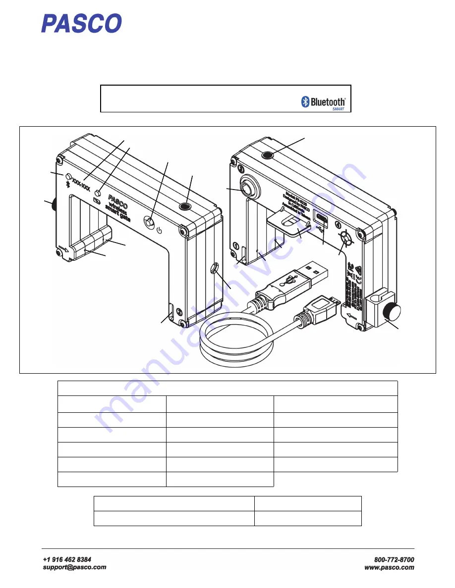
Legend

(1) Swivel Rod Clamp

1

(7) Emitter Port 2

(13) Super Pulley Tab

(2) Bluetooth LED

(8) Photogate Tape Slot

(14) USB Port

(3) Device ID

(9) 1/4-20 Threaded Hole

(15) (Port 4)Laser Detector Port 

(4) Battery LED

(10) Detector Port 1

(16) Indicator LED

(5) Power Button

(11) Detector Port 2

(17) Micro USB Cable

(6)Emitter Port 1

(12) (Port 3) Auxiliary Port 

Required Item*

Model Number*

PASCO Data Collection Software

see www.pasco.com

(1)

(1)

(2)

(3)

(4)

(5)

(6)

(6)

(7)

(8)

(9)

(8)

(10)

(11)

(12)

(13)

(14)

(15)

(16)

(16)

(17)

Power: Rechargeable Battery
Connection: USB or 

Software: SPARKvue or 

PASCO Capstone

Содержание Wireless Smart Gate

Страница 1: ...8 Photogate Tape Slot 14 USB Port 3 Device ID 9 1 4 20 Threaded Hole 15 Port 4 Laser Detector Port 4 Battery LED 10 Detector Port 1 16 Indicator LED 5 Power Button 11 Detector Port 2 17 Micro USB Cabl...

Страница 2: ...cm PASCO Capstone or SPARKvue software records and displays the times for a variety of timing combinations such as the amount of time each port is blocked or the time from when one port is blocked unt...

Страница 3: ...of inactivity if connected and after several minutes if not connected To turn the sensor off press and hold the Power Button for a moment until the Battery LED shines red Release the Power Button and...

Страница 4: ...less Smart Gate but save the swivel rod clamp for later use Use the short thumbscrew from the Photogate Bracket assembly to attach the Wireless Smart Gate to the Photogate Bracket Note that half of th...

Страница 5: ...sory can be used with a Wireless Smart Gate mounted on a Projectile Launcher to measure the time of a projectile s motion from launch to landing Connect the plug from the Time of Flight Accessory into...

Страница 6: ...se a clamp such as the ME 9506 Pendulum Clamp a support rod and string such as the SE 8050 Braided Physics String to hang a Photogate Pendulum as shown with the string attached at two points on the Pe...

Страница 7: ...collecting displaying and analyzing data In the window that opens is the address of the web page for Help Copy and paste the address into a web browser program to open the Sparkvue User s Guide web p...

Страница 8: ...Auxiliary Port Port 3 and the photogate beam is blocked or a projectile hits the Time of Flight pad Laser Detector Port Port 4 is a special case The sensor must be on and Port 4 must be selected in t...

Страница 9: ...Sensor Data Configuration screen opens 3 In the Sensor Data Configuration screen look in the Connected Devices list Touch or click to select the correct address that matches the Device ID XXX XXX num...

Страница 10: ...rt Gate Timer Click or touch Smart Gate Timer and then click or touch OK to accept the choice and close the dialog The Select Measurements for Templates panel is revealed The panel shows Speed Between...

Страница 11: ...interrupted first 3 Smart Gate Only Photogate and Picket Fence 1 Click or touch Photogate and Picket Fence to select it and then click or touch OK to accept the choice and close the dialog The Edit Ti...

Страница 12: ...plates panel is revealed The panel shows Position Velocity and Acceleration with Position as the default choice This measurement gives the amount of distance moved based on the Spoke Arc Length of the...

Страница 13: ...panel is revealed The Flag Length default value is 0 025 m 2 However if the Length of the flag you are using to interrupt the Wireless Smart Gate is a different length highlight the default value in...

Страница 14: ...amount of time for counting highlight the default value in the Edit Timer Properties panel and enter the actual value 3 Click or touch OK to accept the change and close the dialog The Select Measurem...

Страница 15: ...and enter the actual value Click or touch OK to accept the change and close the dialog The Select Measurements for Templates panel is revealed The panel shows Initial Velocity and Time of Flight with...

Страница 16: ...2 with Velocity 1 as the default choice This measurement gives the velocity of the PASCO Cart as calculated based on the Flag Length and the time from when the Flag blocked Detector Port 1 until it bl...

Страница 17: ...d Auxiliary Port Photogate Timing Two Photogates The Photogate Timing Two Photogates is designed for experiments such as Acceleration Down an Inclined Plane In this experiment a cart starts at the top...

Страница 18: ...ven measurements with Time In Gate1 as the default choice This measurement gives the time that the flag of the picket fence blocked Detector Port 1 Velocity In Gate1 is the velocity of the cart based...

Страница 19: ...imer Properties panel opens The Height Of Fall default value is 1 m 3 After you set up the Free Fall Adapter carefully measure the distance from the bottom of the ball to the top of the receptor pad H...

Страница 20: ...sor that matches the XXX XXX Device ID number that is on one side of the Wireless Smart Gate A Connecting to the sensor message appears briefly The Hardware Setup panel changes to show the image of th...

Страница 21: ...uncheck the chosen items and or check any of the other items State 1 This is 0 00 if detector Port 1 is unblocked and 1 00 if detector Port 1 is blocked State 2 The same as State 1 but for detector Po...

Страница 22: ...mer Setup Icon to close the Timer Setup panel Record and Display Data in PASCO Capstone First Setup a Display for a Smart Gate Single Flag By default PASCO Capstone shows a workbook page with eight pr...

Страница 23: ...ecord Data Just below the workbook page is the Controls palette The Record button is near the left end of the palette 1 Click the Record button to begin data recording The experiment clock will show t...

Страница 24: ...ce One Photogate Triple Flag and sensors connected via a TRS phono plug e g Free Fall Adapter Geiger Counter Port 3 Auxiliary Port Example Setup for Photogate 1 Connect a Photogate such as ME 9204B Ac...

Страница 25: ...ve and Photogate Ch 1 3 is not selected The rest of the Timer Setup panel is unchanged You will need to build a new timer in order to use the extra photogate along with the Smart Gate One option is to...

Страница 26: ...ark in front of the first photogate Photogate Ch 1 1 Click Next Step 3 becomes active and it shows a warning message about previously configured devices 9 Ignore the warning and click Next to open Ste...

Страница 27: ...ext to open Step 7 You can leave the default timer s name or enter your own name for the new timer 15 Click Finish The Timer Setup panel shows the new timer s name Review the panel and make changes in...

Страница 28: ...able Wireless Devices 3 Under Available Wireless Devices click the sensor that matches the XXX XXX Device ID number that is on one side of the Wireless Smart Gate A Connecting to the sensor message ap...

Страница 29: ...r menu 6 Select Create a pre configured timer Make sure that there is a checkmark in front of Laser Switch Ch 1 4 and then click Next Step 3 opens You can select the type of timer to create 7 Click th...

Страница 30: ...to a Stop button 4 Click Stop to end data collecting Troubleshooting the Sensor If the sensor loses Bluetooth connection and will not reconnect try cycling the ON button Press and briefly hold the but...

Страница 31: ...re that it will be recycled in a manner that protects human health and the environment To find out where you can drop off your waste equipment for recycling please contact your local waste recycle dis...

Страница 32: ...re Scan down the list of information until you find LMP Version If your Mac is equipped with Bluetooth SMART the LMP Version will show 0x6 Anything lower than 0x6 means an older version of Bluetooth Y...

Страница 33: ...the menu icon in the upper left corner of the home screen In the SPARKvue menu that opens select Choose Language English is the default language choice Note UK Timing Modes are only available in Engli...

Страница 34: ...ck or touch OK to activate that menu choice and close the panel The Edit Timer Properties window is revealed The default choices are Time and Speed Velocity By default acceleration is disabled for thi...

Страница 35: ...lt measurement choice 2 Click or Touch the green Start button to start collecting data Watch the display as you pass a finger back and forth through the Wireless Smart Gate The Display shows the value...

Страница 36: ...ASCO Capstone 1 Turn on the sensor and start the software In the PASCO Capstone Tools palette click the Hard ware Setup icon to open the Hardware Setup panel If no device is connected the panel says S...

Страница 37: ...etup icon in the Tools palette to close the Hardware Setup panel 2 Click the Timer Setup icon in the tools palette to open the Timer Setup panel The Timer Setup panel is revealed The Timer Setup panel...

Страница 38: ...e a Timer Setup for UK Timing Modes 3 Click the green star shaped button to create a new Timer Setup 4 Select Pre Configured Timer Select Next 5 Click Next to open Step 3 Step 3 warns that the default...

Страница 39: ...and Speed Velocity The gate order is at A For this example the Accelertion default choice is not acceptable because One Light Gate can t determine acceleration The other choices are acceptable 9 Click...

Страница 40: ...rrupt the Light Gate If needed highlight the default value and enter your measured length 12 Click Next TO open Step 8 You can use Step 8 to enter a specific name for the timer 13 Click Finish You can...

Страница 41: ...PS 3225 Connect the Sensor Wirelessly in PASCO Capstone 41 013 16123A 15 Appendix D Build a Custom Timer in PASCO Capstone is UNDER CONSTRUCTION See www pasco com for the latest version of this manual...

Страница 42: ...Wireless Smart Gate Connect the Sensor Wirelessly in PASCO Capstone 42 013 16123A...

Отзывы: