


Drive Controlled Pump
Parker Hannifin Corporation
Hydraulics Group
DCP Manual innen A4 UK.indd 06.11.17
68
Manual
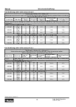
Set of Motor data
If a DCP is delivered as a complete system, the motor
data will be set ex factory and should not be changed.
Motor type
Motor type:
Induction Motor (Standard)
PMAC Motor (if a synchronous motor will be
selected, an autotune has to be done)
Control Strategy:
Volts/Hertz Control
Vector Control (Standard, if vector control will
be selected, an autotune has to be done).
100% Speed in rpm:
This value sets the max. speed of the drive. The
max. speed depends on the type of the pump
and cannot be exceeded.
Acceleration- and deceleration time:
The acceleration- and deceleration – time is
described as the time, the drive needs from
0%-100% and 100%-0% (speed). To avoid an
overload of the DC Link Voltage, the choosen
time should not be too short. The result would
be an error.
Motor name plate
Base Frequency
Rated Motor Current
Motor poles
Base voltage
Nameplate speed
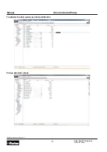
Set of in- and outputs:
In these settings it can be selected, if the in- and outputs
are voltage or current signals. In the Base IO the standard
in- and outputs are listed. In the option file the expanding
in- and outputs are listed (general purpose card required).
Communication:
In the section “communication” the interface
and the corresponding settings are set.
Example: Profibus
Comms Required: Profibus DPV1
Profibus Node Address: 1 (is determined by
the address assignment of the PLC)
Comms Trip Enable: TRUE
Read Mapping: (Only the Controlword is fix,
the others are free)
0: 2021 (Control word)
1: 1918 (Flow Setpoint Fieldbus)
2: 1931 (Pressure Setpoint Fieldbus)
Write Mapping: (Only the Statusword is fix, the
others are free)
0: 2022 (Status word)
1: 1932 (Actual pressure)
2: 1919 (Actual flow)
3: 0393 (Actual speed)