


Drive Controlled Pump
Parker Hannifin Corporation
Hydraulics Group
DCP Manual innen A4 UK.indd 06.11.17
22
Manual
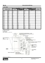
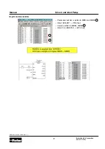
Example:
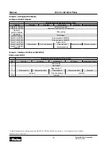
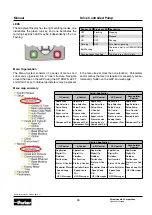
Pulse Encoder
Note:
The encoder power supply is fully isolated from the drive internal circuits and from the encoder inputs on X24 ter-
minals 01 to 04.
Terminal
Name
Range
Description
X24/01
Channel A
±3 V to ±24 V (differential)
or
0 V to 24 V (Single-Ended)
Encoder inputs, compatible with a wide range of encoders.
X24/02
Channel A
X24/03
Channel B
X24/04
Channel B
X24/05
Supply positive
Selectable
5 V, 12 V, 15 V and 24 V
Software-selectable power supply output to encoder.
X24/06
Supply negative
X24/07
Cable Screen
X24/08
Cable Screen