


Drive Controlled Pump
Parker Hannifin Corporation
Hydraulics Group
DCP Manual innen A4 UK.indd 06.11.17
46
Manual
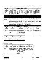
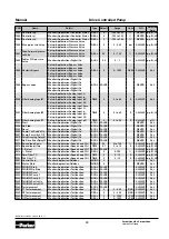
Settings LS Control
Menu item
Setup::Application::
Setup Accu Control
Monitor::Application::Status Accu Control
Setup::Application::
Setup Accu Control
PNO
1946
1947
1948
1949
Parameter name
Pressure Switch Mode
Sensor Mode On
Switch Mode On
Switch On pressure
Parameter
description
Mode for accumulator
charging
Device mode for accumulator
charging
Switch on pressure [bar]
Switch off pressure [bar]
Function
Selection between the use of a
pressure transducer at AIN01
or pressure switches at DI-
GIN04 (switch on signal) and
DIGIN05 (switch off signal). If
the parameter is set to TRUE,
pressure switches will be used.
The parameter “device mode
for accumulator charging” is set
to TRUE, if a pressure trans-
ducer is used in accumulator
charging control (Pressure
Switch Mode = FALSE).
When the “switch on pressure”
is undershooted, the drive ac-
celerates to the max. rotation
speed.
When the “switch off pressure”
is overshooted, the drive de-
celerates to the min. rotation
speed or stops.
Settings Accu Control
Menu item
Setup::Application::Setup Accu Control
PNO
1950
1951
1952
1953
Parameter name
Switch Off pressure
Count T short warning
Count T short error
Tmin OnOff Ctrl
Parameter
description
Max. number of too short
accumulator charging cycles
(warning)
Max. number of too short
accumulator charging cycles
(error message)
Min. time between two
accumulator charging cycles.
[s]
Function
When exceeding the max.
number of too short accumu-
lator charging cycles, a warn-
ing message is generated. The
minimum time between two ac-
cumulator charging cycles can
be defined individually.
When exceeding the max.
number of too short accumu-
lator charging cycles, a warn-
ing message is generated. The
minimum time between two ac-
cumulator charging cycles can
be defined individually.
When exceeding the max.
number of too short accumu-
lator charging cycles, an error
message is generated. The
minimum time between two ac-
cumulator charging cycles can
be defined individually.
Defines the min. time between
two accumulator charging cy-
cles. If the minimum time of two
accumulator charging cycles is
undershooted, a warning or an
error message is generated.
Menu item
Setup::Application::Setup Accu Control
PNO
1954
1955
Parameter name
Actl count time short
Reset Accu Error
Parameter
description
Actual number of too short ac-
cumulator charging cycles.
Resets the number of too
short accumulator charging
cycles
Function
Actual number of accumulator
charging cycles with a pause
time shorter than the specified
min. time between two accumu-
lator charging cycles.
If this parameter is set to TRUE,
the actual number of too short
accumulator charging cycles is
set to 0 and the error message
will disappear.
Menu item
Setup::Application::
Setup LS Control
Monitor::Application:: Status LS Control
Setup::Application::
Setup Accu Control
PNO
1960
1961
1962
1963
Parameter name
Delta p Setpoint
Actual delta p LS
Actual pressure LS
Max p Sensor LS
Parameter
description
Delta pressure setpoint [bar]
Actual delta pressure [bar]
Actual pressure LS [bar]
Scaling of pressure transduc-
er (LS) [bar]
Function
This value sets the delta pres-
sure setpoint for LS control.
This parameter shows the ac-
tual pressure difference (p0
– pLS).
This parameter shows the ac-
tual pressure pLS at AIN02.
Defines the max. pressure for
100% input signal at ANIN02.
Note: Parameter 1951-1955 available from REV J