Modem Installation and Configuration
4-3
3981-A2-GN31-20
November 1996
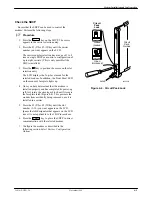
2. At the front of the carrier, hold the modem
vertically, with the latch on its faceplate in the
open position, and insert it into the top and bottom
card guides of one of the slots numbered 1–16.
See Figure 4-2.
Slide the modem into the slot, aligning the modem
with the rear connector plate, until the backplane
connector and DTE connector seat firmly into the
back of the carrier. To lock the modem into the
carrier, press the faceplate latch until a click is
heard.
3. If the carrier is connected to power, the Power
LED on the faceplate of the 3811Plus lights up.
After several seconds the modem completes its
power-up self-test in which all faceplate LEDs
light up.
If the modem fails, or an alarm condition exists,
the Alrm LED on the faceplate lights up or
flashes. It may be possible to run a diagnostic
self-test from the SDCP. See Test Branch in the
COMSPHERE 3800Plus Modems User’s Guide.
Return to the rear of the carrier and tighten the
rear connector plate.
3000 Series
Carrier
3811
Plus
Modem
Latch
Circuit Card
Guides
496-14489-01
SDU
Figure 4-2. Installing a 3811
Plus Modem


