Wireless Data Gateway
3-4
November 1996
3981-A2-GN31-20
Install the Power Units and Power Tray
.
Procedure
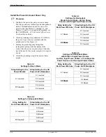
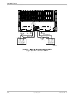
1. Configure the power tray and power unit straps.
The straps can be set for Basic mode, Independent
mode, or Redundant mode, and for one or two
power cables. See Tables 3-1 through 3-4, and
Figures 3-3 and 3-4. For detailed information, see
the COMSPHERE – 48 Vdc Central Office Power
Unit Installation Guide.
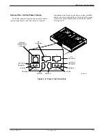
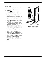
2. Attach a grounding strap (minimum 18 AWG) to
the power tray at the screw marked with the
ground symbol. See Figure 3-2.
3. Feeding the grounding strap through the
rectangular opening in the backplane of the
carrier, slide the power tray into place. Fasten the
tray at the back of the carrier using the two captive
screws.
4. Attach the grounding strap to the nearest frame
ground.
Table 3-1
Settings for Basic Mode
Strap Setting for the
Power Module
Strap Setting for the CO
Power Unit’s Backplane
S1 Lowered
S1 Lowered
S2 Lowered
S3 Lowered
S2 Lowered
S4 Lowered
S2 Lowered
S5 Lowered
Table 3-2
Settings for Independent Mode
Strap Setting for
Each Power Module
Strap Setting for the CO
Power Unit’s Backplane
S1 Raised
S1 Lowered
S2 Raised
S3 Raised
S2 Lowered
S4 Raised
S2 Lowered
S5 Raised
Table 3-3
Settings for Redundant
Mode Using a Single – 48 Vdc Power
Source and a Single Input Power Cable
Strap Setting for
Each Power Module
Strap Setting for the CO
Power Unit’s Backplane
S1 Lowered
S1 Raised
S2 Lowered
S3 Lowered
S2 Raised
S4 Lowered
S2 Raised
S5 Lowered
Table 3-4
Settings for Redundant Mode
with Either a Single Power Source
and Two Input Power Cables, or Two Separate
Power Sources and Two Input Power Cables
Strap Setting for
Each Power Module
Strap Setting for the CO
Power Unit’s Backplane
S1 Lowered
S1 Raised
S2 Lowered
S3 Lowered
S2 Raised
S4 Raised
S2 Raised
S5 Raised


