3-1
3981-A2-GN31-20
November 1996
3000 Series Carrier Installation
Carrier Installation
3-1
. . . . . . . . . . . . . . . . . . . . . . . . . . . . . . . . . . . . . . . . . . . . . . . . . . . . . . . . . . . . . . . . . .
Install the NIMs
3-2
. . . . . . . . . . . . . . . . . . . . . . . . . . . . . . . . . . . . . . . . . . . . . . . . . . . . . . . . . . . . . . . . . .
Install the Carrier
3-3
. . . . . . . . . . . . . . . . . . . . . . . . . . . . . . . . . . . . . . . . . . . . . . . . . . . . . . . . . . . . . . . . .
Install the Power Units and the Power Tray
3-4
. . . . . . . . . . . . . . . . . . . . . . . . . . . . . . . . . . . . . . . . . . . .
Connect the NIM Cables
3-6
. . . . . . . . . . . . . . . . . . . . . . . . . . . . . . . . . . . . . . . . . . . . . . . . . . . . . . . . . . .
Install the SDCP
3-7
. . . . . . . . . . . . . . . . . . . . . . . . . . . . . . . . . . . . . . . . . . . . . . . . . . . . . . . . . . . . . . . . .
Install the SDU
3-7
. . . . . . . . . . . . . . . . . . . . . . . . . . . . . . . . . . . . . . . . . . . . . . . . . . . . . . . . . . . . . . . . . .
Connect the – 48 Vdc Power Source
3-9
. . . . . . . . . . . . . . . . . . . . . . . . . . . . . . . . . . . . . . . . . . . . . . . . . .
Connect the NMS
3-14
. . . . . . . . . . . . . . . . . . . . . . . . . . . . . . . . . . . . . . . . . . . . . . . . . . . . . . . . . . . . . . . .
Carrier Installation
Installation of the COMSPHERE 3000 Series Carrier is
described in the COMSPHERE 3000 Series Carrier
Installation Manual except for the installation and cabling
of the 4-Wire E&M Network Interface Module (NIM) and
the configuration and cabling of the 3811Plus modems.
Experienced installers may wish to follow this
checklist.
Checklist
-
Attach the NIM to the carrier backplane.
•
Set up a static-free work area.
•
Attach the PBX cable to the carrier backplane.
•
Attach the NIM card to the backplane.
•
Attach the PBX cable to the NIM card.
-
Install the SDCP ribbon cable.
-
Install the carrier into the rack.
-
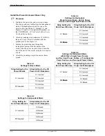
Configure the power tray and power unit straps.
-
Attach the grounding strap to the power tray.
-
Install the power tray.
-
Connect the NIM cables.
•
Attach the 50-position ribbon cable to the NIM
card and the backplane.
•
Install the power connectors to the backplane
and the NIM.
-
Install the SDCP.
•
Attach the ribbon cable to the SDCP.
•
Fasten the SDCP to the front of the carrier.
-
Set the SDU DIP switches and install the SDU card
in Slot 0.
-
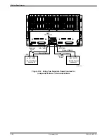
Connect a power source.
-
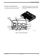
Connect the NMS and cable the SDUs together.
3


