


90
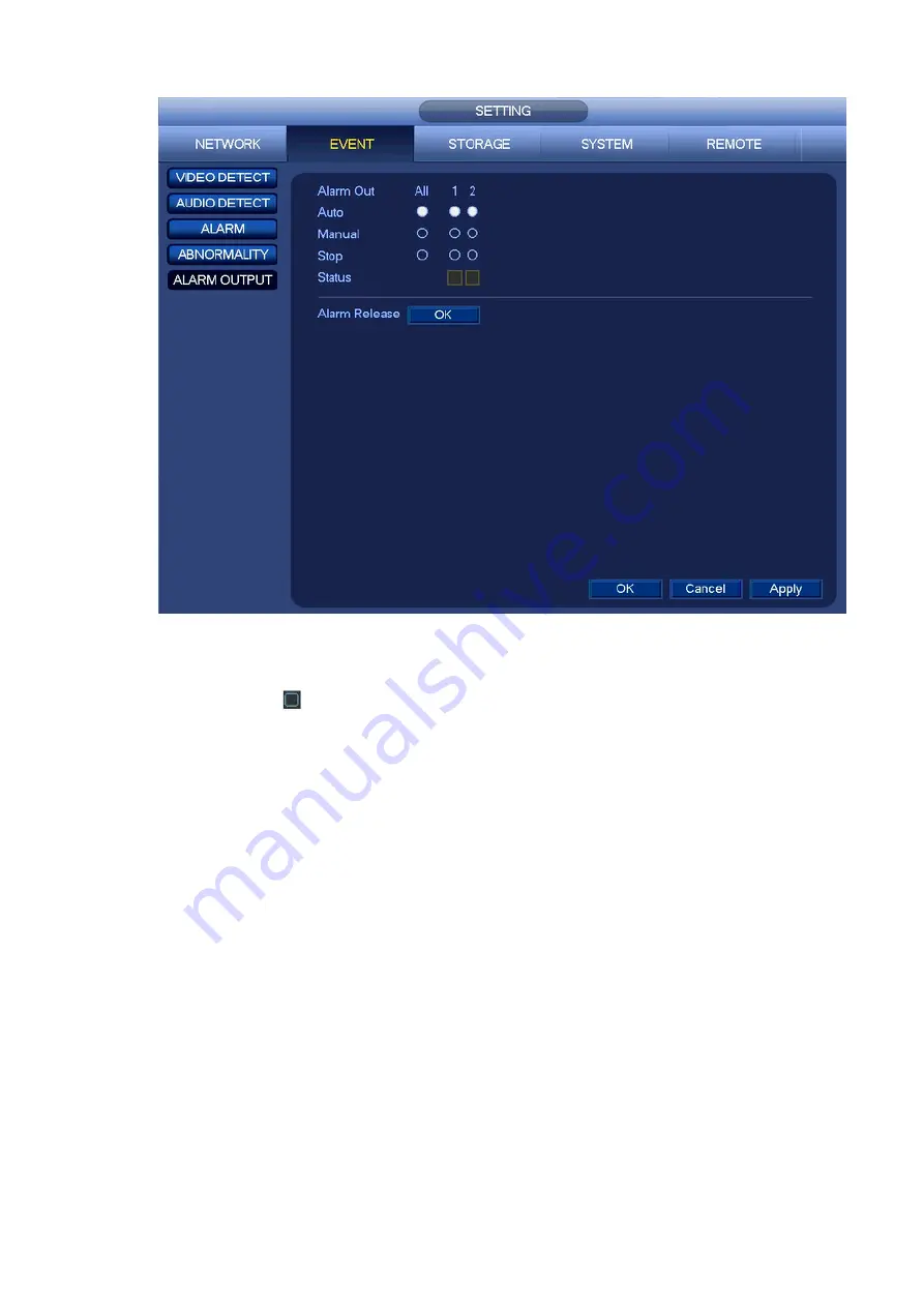
Figure 4-85
Please highlight icon
to select the corresponding alarm output.
After all the setups please click OK button, system goes back to the previous menu.
4.10.4 Alarm Setup
In the main menu, from SETTING->EVENT->ALARM, you can see alarm setup interface. See Figure
4-86.
There are four alarm types. See Figure 4-86 to Figure 4-89.
Local alarm: The alarm signal system detects from the alarm input port.
Network alarm: It is the alarm signal from the network.
IPC external alarm: It is the on-off alarm signal from the front-end device and can activate the local
NVR.
IPC offline alarm: Once you select this item, system can generate an alarm when the front-end IPC
disconnects with the local NVR. The alarm can activate record, PTZ, snap and etc. The alarm can
last until the IPC and the NVR connection resumes.
Important
If it is your first time to boot up the device, the disconnection status of the front-end
network camera will not be regarded as offline. After one successfully connection, all
the disconnection events will be regarded as IPC offline event.
When IPC offline alarm occurs, the record and snapshot function of digital channel is
null.
In the main menu, from SETTING->EVENT->ALARM, you can see alarm setup interface.
Содержание K-NL404K/G
Страница 1: ...Network Disk Recorder User s Manual Model No K NL404K G K NL408K G K NL416K G Version 1 0 1 ...
Страница 25: ...19 3 4 Connection Sample Please refer to Figure 3 1 for connection sample Figure 3 1 ...
Страница 69: ...63 Figure 4 61 Figure 4 62 ...
Страница 90: ...84 Figure 4 78 Figure 4 79 ...
Страница 91: ...85 Figure 4 80 Figure 4 81 ...
Страница 99: ...93 Figure 4 87 Figure 4 88 ...
Страница 100: ...94 Figure 4 89 Figure 4 90 ...
Страница 101: ...95 Figure 4 91 Figure 4 92 ...
Страница 104: ...98 Figure 4 94 Figure 4 95 ...
Страница 112: ...106 Figure 4 104 Figure 4 105 ...
Страница 121: ...115 Figure 4 115 ...
Страница 124: ...118 Figure 4 117 In Figure 4 117 click one HDD item the S M A R T interface is shown as in Figure 4 118 ...
Страница 127: ...121 Figure 4 120 Figure 4 121 ...
Страница 132: ...126 Figure 4 125 Figure 4 126 ...
Страница 139: ...133 Figure 4 133 Figure 4 134 ...
Страница 141: ...135 Figure 4 136 ...
Страница 143: ...137 ...
Страница 146: ...140 Figure 4 140 Step 2 Click Add user button Enter Add user interface See Figure 2 141 ...
Страница 151: ...145 Figure 4 144 1 ...
Страница 157: ...151 ...
Страница 158: ...152 Please input your username and password Figure 5 3 ...
Страница 163: ...157 Figure 5 11 You can click this icon to display or hide the PTZ control platform 3D Intelligent Positioning Key ...
Страница 191: ...185 Figure 5 41 ...
Страница 192: ...186 Figure 5 42 ...
Страница 193: ...187 Figure 5 43 Figure 5 44 Figure 5 45 ...
Страница 198: ...192 ...
Страница 199: ...193 Figure 5 49 ...
Страница 205: ...199 Figure 5 55 Figure 5 56 ...
Страница 208: ...202 Figure 5 60 Figure 5 61 Figure 5 62 ...
Страница 239: ...233 ...


