


99
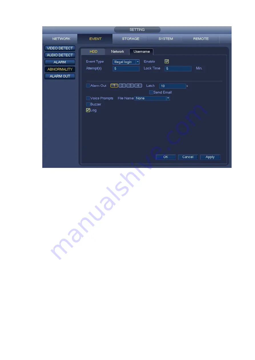
Figure 4-96
4.11
Network
4.11.1 TCP/IP
The single network adapter interface is shown as in Figure 4-98 .
IP Version: There are two options: IPv4 and IPv6. Right now, system supports these two IP address
format and you can access via them.
MAC Address: The host in the LAN can get a unique MAC address. It is for you to access in the LAN. It is
read-only.
IP Address: Here you can use up/down button or input the corresponding number to input IP address.
Then you can set the corresponding subnet mask the default gateway.
Default Gateway: Here you can input the default gateway. Please note system needs to check the
validity of all IPv6 addresses. The IP address and the default gateway shall be in the same IP
section. That is to say, the specified length of the subnet prefix shall have the same string.
DHCP: It is to auto search IP. When enable DHCP function, you cannot modify IP/Subnet mask
/Gateway. These values are from DHCP function. If you have not enabled DHCP function, IP/Subnet
mask/Gateway display as zero. You need to disable DHCP function to view current IP information.
Besides, when PPPoE is operating, you cannot modify IP/Subnet mask /Gateway.
MTU: It is to set MTU value of the network adapter. The value ranges from 1280-7200 bytes. The
default setup is 1500 bytes. Please note MTU modification may result in network adapter reboot and
network becomes off. That is to say, MTU modification can affect current network service. System
may pop up dialog box for you to confirm setup when you want to change MTU setup. Click OK
Содержание K-NL404K/G
Страница 1: ...Network Disk Recorder User s Manual Model No K NL404K G K NL408K G K NL416K G Version 1 0 1 ...
Страница 25: ...19 3 4 Connection Sample Please refer to Figure 3 1 for connection sample Figure 3 1 ...
Страница 69: ...63 Figure 4 61 Figure 4 62 ...
Страница 90: ...84 Figure 4 78 Figure 4 79 ...
Страница 91: ...85 Figure 4 80 Figure 4 81 ...
Страница 99: ...93 Figure 4 87 Figure 4 88 ...
Страница 100: ...94 Figure 4 89 Figure 4 90 ...
Страница 101: ...95 Figure 4 91 Figure 4 92 ...
Страница 104: ...98 Figure 4 94 Figure 4 95 ...
Страница 112: ...106 Figure 4 104 Figure 4 105 ...
Страница 121: ...115 Figure 4 115 ...
Страница 124: ...118 Figure 4 117 In Figure 4 117 click one HDD item the S M A R T interface is shown as in Figure 4 118 ...
Страница 127: ...121 Figure 4 120 Figure 4 121 ...
Страница 132: ...126 Figure 4 125 Figure 4 126 ...
Страница 139: ...133 Figure 4 133 Figure 4 134 ...
Страница 141: ...135 Figure 4 136 ...
Страница 143: ...137 ...
Страница 146: ...140 Figure 4 140 Step 2 Click Add user button Enter Add user interface See Figure 2 141 ...
Страница 151: ...145 Figure 4 144 1 ...
Страница 157: ...151 ...
Страница 158: ...152 Please input your username and password Figure 5 3 ...
Страница 163: ...157 Figure 5 11 You can click this icon to display or hide the PTZ control platform 3D Intelligent Positioning Key ...
Страница 191: ...185 Figure 5 41 ...
Страница 192: ...186 Figure 5 42 ...
Страница 193: ...187 Figure 5 43 Figure 5 44 Figure 5 45 ...
Страница 198: ...192 ...
Страница 199: ...193 Figure 5 49 ...
Страница 205: ...199 Figure 5 55 Figure 5 56 ...
Страница 208: ...202 Figure 5 60 Figure 5 61 Figure 5 62 ...
Страница 239: ...233 ...


