


62
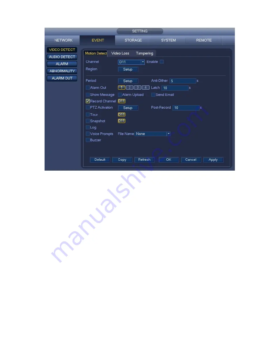
Figure 4-60
b) Select motion detect from the event type dropdown list. Select a channel from the dropdown list
and then check the enable box to enable motion detect function.
c) Click Region Setup button to set motion detect zone. There are 396(PAL)/330(NTSC) small
zones. The green zone is current cursor position. Gray zone is the motion detection zone. Black
zone is the disarmed zone. You can click FN button to switch between the arm mode and disarm
mode. In arm mode, you can click the direction buttons to move the green rectangle to set the
motion detection zone. After you completed the setup, please click ENTER button to exit current
setup. Do remember click save button to save current setup. If you click ESC button to exit the
region setup interface system will not save your zone setup.
d) Period: Click Setup button, you can see an interface is shown as in Figure 4-61. Here you can
set motion detect period. System only enables motion detect operation in the specified periods.
It is not for video loss or the tampering. There are two ways for you to set periods. Please note
system only supports 6 periods in one day.
e) Set sensitivity. Please note the sixth level has the highest sensitivity.
f) Click Save button to complete motion detect setup.
g) From Main menu->SETTING->STORAGE->SCHEDULE. See Figure 4-51
.
h) Set motion detect record channel, period and the record type shall be motion detect (MD).
Please refer to chapter 4.7.2.
i) Click Copy button to copy current setup to other channel(s).
j) Click OK button to complete motion detect record setup.
Содержание K-NL404K/G
Страница 1: ...Network Disk Recorder User s Manual Model No K NL404K G K NL408K G K NL416K G Version 1 0 1 ...
Страница 25: ...19 3 4 Connection Sample Please refer to Figure 3 1 for connection sample Figure 3 1 ...
Страница 69: ...63 Figure 4 61 Figure 4 62 ...
Страница 90: ...84 Figure 4 78 Figure 4 79 ...
Страница 91: ...85 Figure 4 80 Figure 4 81 ...
Страница 99: ...93 Figure 4 87 Figure 4 88 ...
Страница 100: ...94 Figure 4 89 Figure 4 90 ...
Страница 101: ...95 Figure 4 91 Figure 4 92 ...
Страница 104: ...98 Figure 4 94 Figure 4 95 ...
Страница 112: ...106 Figure 4 104 Figure 4 105 ...
Страница 121: ...115 Figure 4 115 ...
Страница 124: ...118 Figure 4 117 In Figure 4 117 click one HDD item the S M A R T interface is shown as in Figure 4 118 ...
Страница 127: ...121 Figure 4 120 Figure 4 121 ...
Страница 132: ...126 Figure 4 125 Figure 4 126 ...
Страница 139: ...133 Figure 4 133 Figure 4 134 ...
Страница 141: ...135 Figure 4 136 ...
Страница 143: ...137 ...
Страница 146: ...140 Figure 4 140 Step 2 Click Add user button Enter Add user interface See Figure 2 141 ...
Страница 151: ...145 Figure 4 144 1 ...
Страница 157: ...151 ...
Страница 158: ...152 Please input your username and password Figure 5 3 ...
Страница 163: ...157 Figure 5 11 You can click this icon to display or hide the PTZ control platform 3D Intelligent Positioning Key ...
Страница 191: ...185 Figure 5 41 ...
Страница 192: ...186 Figure 5 42 ...
Страница 193: ...187 Figure 5 43 Figure 5 44 Figure 5 45 ...
Страница 198: ...192 ...
Страница 199: ...193 Figure 5 49 ...
Страница 205: ...199 Figure 5 55 Figure 5 56 ...
Страница 208: ...202 Figure 5 60 Figure 5 61 Figure 5 62 ...
Страница 239: ...233 ...


