


171
mode, the bit stream is near the specified value. In VBR mode,
the video quality changes according to the bit stream value. But
its max value is near the specified value. Reference bit rate: The
reference bit rate depends on the resolution and frame rate you
set.
Bit Rate
Main stream: You can set bit rate here to change video
quality. The large the bit rate is, the better the quality is.
Please refer to recommend bit rate for the detailed
information.
Sub stream: In CBR, the bit rate here is the max value. In
dynamic video, system needs to low frame rate or video
quality to guarantee the value. The value is null in VBR
mode.
Reference Bit
Rate
Recommended bit rate value according to the resolution and
frame rate you have set.
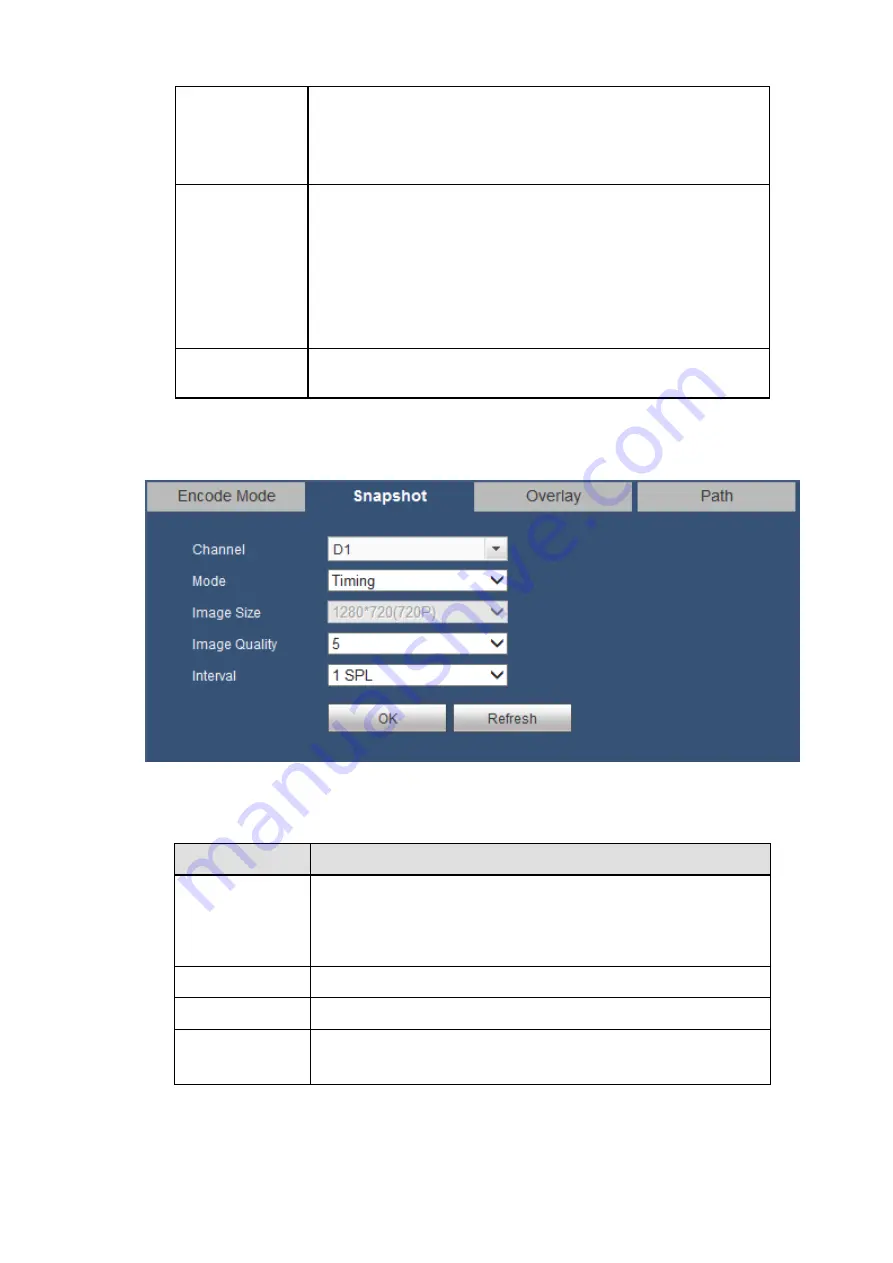
5.8.1.4.2 Snapshot
The snapshot interface is shown as in Figure 5-23.
Figure 5-23
Please refer to the following sheet for detailed information.
Parameter
Function
Mode
There are two modes: Regular (schedule) and Trigger.
Regular snapshot is valid during the specified period you
set.
Trigger snapshot only is valid when motion detect alarm,
tampering
alarm or local activation alarm occurs.
Image Size
It is the same with the resolution of the main stream.
Image Quality
It is to set the image quality. There are six levels.
Interval
It is to set snapshot frequency. The value ranges from 1s to 7s.
Or you can set customized value. The max setup is
3600s/picture.
Содержание K-NL404K/G
Страница 1: ...Network Disk Recorder User s Manual Model No K NL404K G K NL408K G K NL416K G Version 1 0 1 ...
Страница 25: ...19 3 4 Connection Sample Please refer to Figure 3 1 for connection sample Figure 3 1 ...
Страница 69: ...63 Figure 4 61 Figure 4 62 ...
Страница 90: ...84 Figure 4 78 Figure 4 79 ...
Страница 91: ...85 Figure 4 80 Figure 4 81 ...
Страница 99: ...93 Figure 4 87 Figure 4 88 ...
Страница 100: ...94 Figure 4 89 Figure 4 90 ...
Страница 101: ...95 Figure 4 91 Figure 4 92 ...
Страница 104: ...98 Figure 4 94 Figure 4 95 ...
Страница 112: ...106 Figure 4 104 Figure 4 105 ...
Страница 121: ...115 Figure 4 115 ...
Страница 124: ...118 Figure 4 117 In Figure 4 117 click one HDD item the S M A R T interface is shown as in Figure 4 118 ...
Страница 127: ...121 Figure 4 120 Figure 4 121 ...
Страница 132: ...126 Figure 4 125 Figure 4 126 ...
Страница 139: ...133 Figure 4 133 Figure 4 134 ...
Страница 141: ...135 Figure 4 136 ...
Страница 143: ...137 ...
Страница 146: ...140 Figure 4 140 Step 2 Click Add user button Enter Add user interface See Figure 2 141 ...
Страница 151: ...145 Figure 4 144 1 ...
Страница 157: ...151 ...
Страница 158: ...152 Please input your username and password Figure 5 3 ...
Страница 163: ...157 Figure 5 11 You can click this icon to display or hide the PTZ control platform 3D Intelligent Positioning Key ...
Страница 191: ...185 Figure 5 41 ...
Страница 192: ...186 Figure 5 42 ...
Страница 193: ...187 Figure 5 43 Figure 5 44 Figure 5 45 ...
Страница 198: ...192 ...
Страница 199: ...193 Figure 5 49 ...
Страница 205: ...199 Figure 5 55 Figure 5 56 ...
Страница 208: ...202 Figure 5 60 Figure 5 61 Figure 5 62 ...
Страница 239: ...233 ...


