


160
Please refer to the following contents for LAN and WAN login difference.
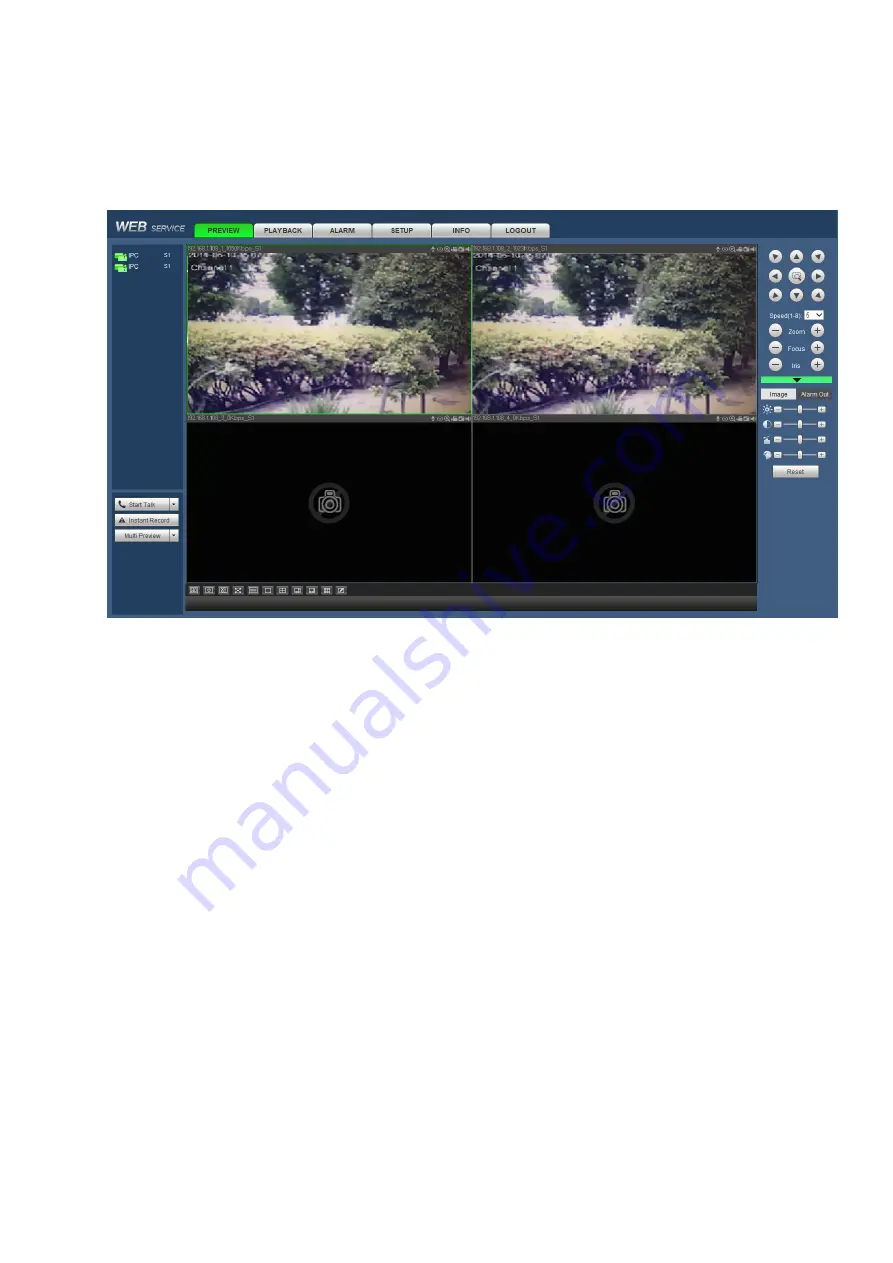
1) In the WAN mode, system opens the main stream of the first channel to monitor by default. The
open/close button on the left pane is null.
2) You can select different channels and different monitor modes at the bottom of the interface. See
Figure 5-16.
Figure 5-16
Important
The window display mode and the channel number are by default. For example, for the 8-channel,
the max window split mode is 8.
3) Multiple-channel monitor, system adopts extra stream to monitor by default. Double click one channel,
system switches to single channel and system uses main stream to monitor. You can view there are two
icons at the left top corner of the channel number for you reference. M stands for main stream. S stands
for sub stream (extra stream).
4) If you login via the WAN mode, system does not support alarm activation to open the video function in
the Alarm setup interface.
Important
For multiple-channel monitor mode, system adopts extra stream to monitor by default. You cannot
modify manually. All channels are trying to synchronize. Please note the synchronization effect still
depends on your network environments.
For bandwidth consideration, system cannot support monitor and playback at the same time. System
auto closes monitor or playback interface when you are searching setup in the configuration interface.
It is to enhance search speed.
Содержание K-NL404K/G
Страница 1: ...Network Disk Recorder User s Manual Model No K NL404K G K NL408K G K NL416K G Version 1 0 1 ...
Страница 25: ...19 3 4 Connection Sample Please refer to Figure 3 1 for connection sample Figure 3 1 ...
Страница 69: ...63 Figure 4 61 Figure 4 62 ...
Страница 90: ...84 Figure 4 78 Figure 4 79 ...
Страница 91: ...85 Figure 4 80 Figure 4 81 ...
Страница 99: ...93 Figure 4 87 Figure 4 88 ...
Страница 100: ...94 Figure 4 89 Figure 4 90 ...
Страница 101: ...95 Figure 4 91 Figure 4 92 ...
Страница 104: ...98 Figure 4 94 Figure 4 95 ...
Страница 112: ...106 Figure 4 104 Figure 4 105 ...
Страница 121: ...115 Figure 4 115 ...
Страница 124: ...118 Figure 4 117 In Figure 4 117 click one HDD item the S M A R T interface is shown as in Figure 4 118 ...
Страница 127: ...121 Figure 4 120 Figure 4 121 ...
Страница 132: ...126 Figure 4 125 Figure 4 126 ...
Страница 139: ...133 Figure 4 133 Figure 4 134 ...
Страница 141: ...135 Figure 4 136 ...
Страница 143: ...137 ...
Страница 146: ...140 Figure 4 140 Step 2 Click Add user button Enter Add user interface See Figure 2 141 ...
Страница 151: ...145 Figure 4 144 1 ...
Страница 157: ...151 ...
Страница 158: ...152 Please input your username and password Figure 5 3 ...
Страница 163: ...157 Figure 5 11 You can click this icon to display or hide the PTZ control platform 3D Intelligent Positioning Key ...
Страница 191: ...185 Figure 5 41 ...
Страница 192: ...186 Figure 5 42 ...
Страница 193: ...187 Figure 5 43 Figure 5 44 Figure 5 45 ...
Страница 198: ...192 ...
Страница 199: ...193 Figure 5 49 ...
Страница 205: ...199 Figure 5 55 Figure 5 56 ...
Страница 208: ...202 Figure 5 60 Figure 5 61 Figure 5 62 ...
Страница 239: ...233 ...


