200
Please refer to the following sheet for detailed information.
Parameter Function
Event
Type
The abnormal events include: No disk, disk error, disk no space, net
disconnection, IP conflict, MAC conflict, and Illegal Login.
You can set one or more items here.
Less than: You can set the minimum percentage value here (For disk
not space only). The device can alarm when capacity is not sufficient.
You need to draw a circle to enable this function.
Enable
Check the box here to enable selected function.
Alarm Out Please select corresponding alarm output channel when an alarm
occurs. You need to check the box to enable this function.
Latch
The alarm output can delay for the specified time after an alarm stops.
The value ranges from 1s to 300s.
Show
Message
System can pop up a message to alarm you in the local host screen if
you enabled this function.
Alarm
Upload
System can upload the alarm signal to the centre (Including alarm
centre.
Send
If you enabled this function, System can send out an email to alert you
when an alarm occurs.
Buzzer
Check the box here to enable this function. The buzzer beeps when an
alarm occurs.
5.8.3.5
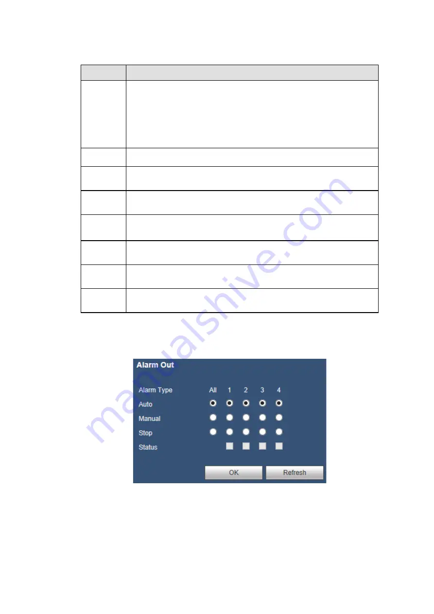
Alarm Out
The alarm output interface is shown as below. See Figure 5-58.
Here you can set alarm output mode: Auto/Manual/Stop.
Figure 5-58
Содержание K-NL404K/G
Страница 1: ...Network Disk Recorder User s Manual Model No K NL404K G K NL408K G K NL416K G Version 1 0 1 ...
Страница 25: ...19 3 4 Connection Sample Please refer to Figure 3 1 for connection sample Figure 3 1 ...
Страница 69: ...63 Figure 4 61 Figure 4 62 ...
Страница 90: ...84 Figure 4 78 Figure 4 79 ...
Страница 91: ...85 Figure 4 80 Figure 4 81 ...
Страница 99: ...93 Figure 4 87 Figure 4 88 ...
Страница 100: ...94 Figure 4 89 Figure 4 90 ...
Страница 101: ...95 Figure 4 91 Figure 4 92 ...
Страница 104: ...98 Figure 4 94 Figure 4 95 ...
Страница 112: ...106 Figure 4 104 Figure 4 105 ...
Страница 121: ...115 Figure 4 115 ...
Страница 124: ...118 Figure 4 117 In Figure 4 117 click one HDD item the S M A R T interface is shown as in Figure 4 118 ...
Страница 127: ...121 Figure 4 120 Figure 4 121 ...
Страница 132: ...126 Figure 4 125 Figure 4 126 ...
Страница 139: ...133 Figure 4 133 Figure 4 134 ...
Страница 141: ...135 Figure 4 136 ...
Страница 143: ...137 ...
Страница 146: ...140 Figure 4 140 Step 2 Click Add user button Enter Add user interface See Figure 2 141 ...
Страница 151: ...145 Figure 4 144 1 ...
Страница 157: ...151 ...
Страница 158: ...152 Please input your username and password Figure 5 3 ...
Страница 163: ...157 Figure 5 11 You can click this icon to display or hide the PTZ control platform 3D Intelligent Positioning Key ...
Страница 191: ...185 Figure 5 41 ...
Страница 192: ...186 Figure 5 42 ...
Страница 193: ...187 Figure 5 43 Figure 5 44 Figure 5 45 ...
Страница 198: ...192 ...
Страница 199: ...193 Figure 5 49 ...
Страница 205: ...199 Figure 5 55 Figure 5 56 ...
Страница 208: ...202 Figure 5 60 Figure 5 61 Figure 5 62 ...
Страница 239: ...233 ...


