background image

Menus 


GTWIN Reference Manual 

168 


4.7.8.4  Change the Language with a PLC 

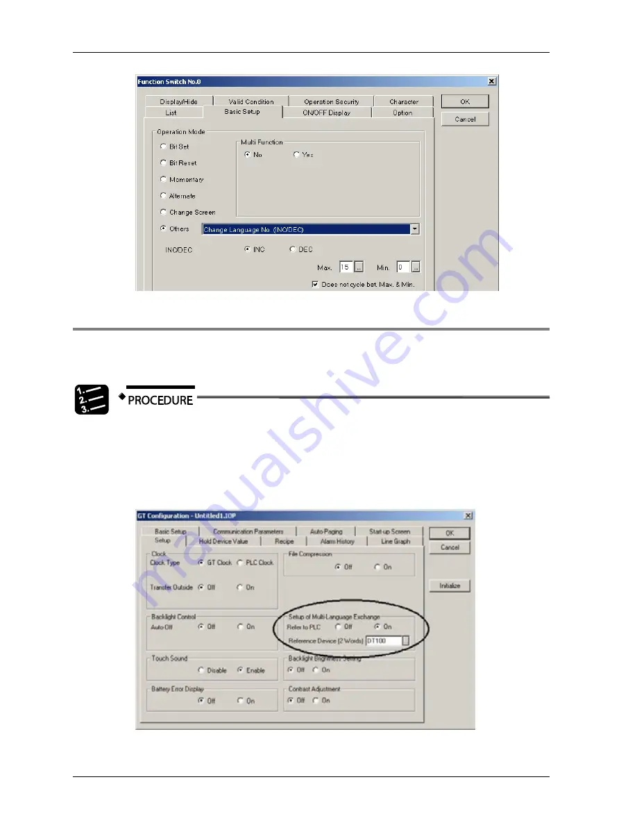
You can also change the language of the screen externally by using a PLC register (reference 
device).   


1.  File 

 Configuration 

 GT Configuration   

2.  On the "Setup" tab, set "Refer to PLC" to "On" 

This displays an additional field where you can set the PLC register which will 
trigger the change of the screen language and provide the language number to 
switch to. 


3.  Under "Reference Device", set the PLC register   

Содержание GTWIN

Страница 1: ...TOUCH TERMINALS GTWIN Reference Manual ...

Страница 2: ...t or its documentation even if advised of the possibility of such damages We invite your comments on this manual Please e mail us at techdoc peweu eu panasonic com Please direct support matters and technical questions to your local Panasonic representative Limited warranty If physical defects caused by distribution are found PEWEU will replace repair the product free of charge Exceptions include W...

Страница 3: ... could be fatal or critical injury Indicates that you should proceed with caution Failure to do so may result in injury or significant damage to instruments or their contents e g data Contains important additional information Contains an illustrative example of the previous text section Indicates that a step by step procedure follows Indicates where you can find additional information on the subje...

Страница 4: ...2 3 Edit GT Internal Memory 16 1 3 3 GT Ver_UP 16 1 3 4 Modem Connection 17 1 4 Create New File 18 1 5 GTWIN Configuration 19 1 6 GT Configuration 21 1 6 1 Basic Setup 23 1 6 1 1 Basic Communication Area to PLC 24 1 6 2 Communication Parameters 26 1 6 3 PLC Multiple Connection 28 1 6 3 1 Skip Communication Error Station 29 1 6 3 2 PLC Unit No and Comment 30 1 6 4 Auto Paging 31 1 6 5 Start Up Scre...

Страница 5: ...egistration 56 2 GT Panel System Menu 58 2 1 GT Panel System Menu Overview 59 2 2 Port 61 2 3 Clear Memory 62 2 4 Test Menu 64 2 5 DIP Switch Settings to Prevent System Menu Display 65 2 6 SD Memory Card Functions 66 2 6 1 Usable SD Memory Cards 68 2 6 2 Restrictions 69 2 6 3 Copy Screen Data to the SD Memory Card 71 2 6 4 Copy Screen Data to the GT 73 2 6 5 Copy PLC Program Files to the PLC 74 2 ...

Страница 6: ...What You See on Your Monitor 94 3 2 Menu Bar 95 3 3 Toolbar 96 3 4 Graphic Bar 98 3 5 Size Coordinate Bar 101 3 6 Base Screen 102 3 7 Parts Library 103 3 7 1 New Parts Library 104 3 7 2 Flowchart Symbols Library 105 3 8 Screen Manager 106 4 Menus 107 4 1 File Menu 108 4 1 1 New Open Close Save Save As Delete 108 4 1 1 1 Windows Fonts Not Available 109 4 1 2 Print 110 4 1 3 Print Style Setup 111 4 ...

Страница 7: ...Editor 132 4 7 1 2 Using the Bitmap Editor 134 4 7 1 3 Importing Bitmap Files 136 4 7 1 4 Organizing Bitmap Files 137 4 7 1 5 Placing Bitmaps on Base Screens 137 4 7 2 Recipe 139 4 7 2 1 How to Create a Recipe File 139 4 7 2 2 Transferring Recipe Files 142 4 7 2 3 Example Recipe 142 4 7 3 SD Recipe 145 4 7 3 1 How to Save SD Recipe Data on the SD Memory Card 146 4 7 3 2 SD Recipe Basic Setup 147 4...

Страница 8: ...g 169 4 7 9 1 Log File and CSV File Structure 171 4 7 9 2 Log File Setup 173 4 7 9 3 Control Setup for Data Logging 176 4 8 Window menu 179 4 9 Help Menu 180 5 Parts and Their Functions 181 5 1 Switch Parts 182 5 2 Function Switch Parts 184 5 2 1 Multi Function 187 5 3 Lamp Parts 188 5 4 Message Parts 190 5 4 1 Message Part Sample FPWIN Pro Program 191 5 5 Data Parts 194 5 5 1 Basic Setup for Data...

Страница 9: ...e 215 5 9 4 Basic Setup in Block Mode 217 5 9 5 Line Graphs Combined with Bar Graphs 220 5 10 Keyboard Parts 223 5 10 1 Basic Setup for Keyboard Parts 224 5 10 2 Operation Setup for Keyboard Parts 226 5 10 3 Displaying and Hiding Keyboard Parts 226 5 11 Custom Parts 227 5 11 1 Custom Switch Parts 227 5 11 2 Custom Lamp and Custom Message Parts 228 5 11 3 Replacement Tab for Custom Parts 230 6 Trou...

Страница 10: ...H 257 7 7 Connecting 24V Types to the TOOL Port of FP2 FP2SH 259 7 8 Connecting to the COM Port of FP X 261 7 9 Connecting to the COM Port of FPΣ FP0 R FP e 265 7 10 Connecting to the COM Port of FP2 FP2SH 269 7 11 Connecting to the FP2 FP2SH Computer Communication Unit 271 7 12 Connecting to the C NET ADAPTER 273 7 13 Connecting Via GT Link 274 7 13 1 GT Link Using FP2 FP2SH 274 7 13 2 GT Link Us...

Страница 11: ...Chapter 1 Introducing GTWIN ...

Страница 12: ... drag and drop them onto your screen A switch part being dragged and dropped You can also customize your own parts and store them in a user library Other features include Line graph function to represent sampling data Recipe transfer between PC GT and PLC Copy screens to a clipboard in bitmap format This makes it easy for you to create an operation manual for example Bitmap editor Fonts include a ...

Страница 13: ...ications of Windows Vista you cannot store files in system folders such as Program Files Screen data If you attempt to save screen data in a system folder GTWIN will issue an alarm message and urge you to choose another folder Part libraries BMP library multilanguage exchange string list recipe data If you attempt to store these files in system folders GTWIN will not issue an alarm message Instead...

Страница 14: ...log appears Choose a command button and click OK To boot via the taskbar Startup Programs Panasonic ID SUNX Terminal GTWIN From the GTWIN subfolder you can open several helpful PDF files or access a Tools subfolder which contains GT Memory Editor see p 15 GT Ver_UP see p 16 Modem Connection see p 17 ...

Страница 15: ... Manual 14 1 3 1 Read From GT If you selected Read From GT the following dialog appears You may have to enter a password Select which data you wish to be transferred from GT to GTWIN as desired Windows fonts are not available see p 109 ...

Страница 16: ...he GT edit the internal memory of the GT which is particularly useful for general purpose serial communication 1 3 2 1 Upload Alarm History Information When you select this option the following dialog appears Click GT PC to upload alarms Under Base Screen when you select Auto all alarms will be uploaded or you can select Manual to upload alarms associated with specific base screens Click Save to s...

Страница 17: ...e 1 3 2 3 Edit GT Internal Memory When you select this option the following dialog appears You can upload device values from the GT to the PC edit them and or download them from the PC to the GT Simply double click on any field e g Device to edit or insert a value You can also insert delete or rename sheets 1 3 3 GT Ver_UP Use this dialog to manually perform a version upgrade After calling up the ...

Страница 18: ...unit while upgrading Do not disconnect the cable between the PC and the GT unit otherwise the GT unit may not reboot The through function is not available during the version upgrade and while transferring screens 1 3 4 Modem Connection You may use the Modem Connection dialog to help establish a modem connection to a GT PLC application Modem Connection dialog Please refer to the separate online hel...

Страница 19: ...a PLC model from the list in the text box Please note some PLCs of other manufacturers may not work with all GT models Keep Current Settings Select this check box so that the next time you create a new file the GT model and PLC model you selected will appear as your default settings Next the following dialog is displayed on the screen Be sure to check your basic communication area see p 23 setting...

Страница 20: ...except the drive settings will be reset to the default factory values Configuration parameters Tab Field Description Drive Parts Library Defines the path where the data files for the parts library are stored BMP Library Defines the file where your bitmaps are stored File Current Folder Defines the default folder for saving or reading GTWIN files Auto Backup Defines whether to back up your files au...

Страница 21: ... 226 when creating screens Tips Display Select whether to display tips and when to display them When creating files GTWIN recommends defining the basic communication area When saving files GTWIN explains how files are stored Graphic Circle Oval Select how circles and ovals see p 98 are drawn Start from Center Point Beginning at the center of the circle you trace an invisible rectangle that expands...

Страница 22: ...n settings before using the GT unit Call up the GT Configuration dialog via File Configuration GT Configuration Which tabs and what appears on them may differ depending on which GT model you have selected whether you are communicating with a PLC or using general purpose RS232C communication ...

Страница 23: ...e PC GTWIN and the GT unit PLC Multiple Connection see p 28 If you select Yes you can specify the unit number and name for multiple Panasonic FP series PLCs connected to the GT Auto Paging see p 31 Specify when to switch screens Start up Screen see p 31 Specify which screen is displayed and how long it is displayed when the GT is booted Setup 1 see p 32 Enter settings for the clock backlight touch...

Страница 24: ...e connected to the GT GT Model Displays the GT model Basic Communication Area to PLC see p 24 The basic communication area allows the PLC and GT unit to exchange basic data The devices addresses assigned to this area must be set they must not be used for other purposes neither by the PLC nor by the GT Word Area Specify the device and starting address for the word area that reads and writes screen ...

Страница 25: ...d the GT executes a process in accordance with that command The command response mode returns the result to the RS232C device Two way 1 The RS232C device connected to the GT sends a control command to the GT Data such as switch operations and data settings is transmitted to the RS232C device from the GT In this mode the GT does not reply to the command from the connected RS232C device so execution...

Страница 26: ...lashing 0 lighted normal 1 flashing Backlight color GT01 GT02G GT05G GT12G 3 color LED backlight 00 Off 01 Green 10 Red 11 Orange GT01 1 color LED backlight 00 Off 01 Lighted 10 Off 11 Lighted weak GT02L GT03 E GT05S GT32 E 1 color LED backlight 00 Off 01 Lighted 10 Lighted 11 Lighted GT01R GT02M GT05M GT12M 3 color LED backlight 00 Off 01 White 10 Red 11 Pink GT11 3 color LED backlight 00 Off 01 ...

Страница 27: ...Login screen display flag 1 login screen displayed 0 login finished Battery low flag This bit turns on when the battery is low and the battery low icon appears on the lower right of the GT screen if the battery error display is set to ON Please replace the battery within 1 week Battery low icon Battery This bit turns on if clock data and Hold PLC Device data held in the SRAM are not being backed u...

Страница 28: ...aud rate and the parity bit The data length and the stop bit value are read only and fixed at 8 and 1 respectively Transmission Delay When the GT unit and any controller communicate with each other they transfer data Basically the GT is the master and requests an answer the controller PLC replies Some circumstances may cause the GT unit to communicate faster than the controller and information may...

Страница 29: ...appears on them may differ depending on which GT model you have selected Activating PLC Multiple Connection will make the following fields appear Skip Communication Error Station see p 29 PLC Unit No and Comment see p 30 Once you have set up multiple PLCs communication will occur as illustrated ...

Страница 30: ...ion Error Station you can poll the PLC to check whether the communication error has been recovered Click Setup to call up the dialog The GT polls the defective PLC at the Confirmation Interval specified to see whether the communication error has been recovered During polling the PLC must respond during the specified Timeout If the communication error has been recovered communication is resumed Oth...

Страница 31: ...d Comment Press Comment to set up multiple PLCs and assign meaningful names Once you have defined multiple PLCs you will have to select the desired PLC when making device settings Similarly the PLC unit number comment will appear after device settings in other dialogs ...

Страница 32: ... Specify how long to display the screen being jumped from Jump to 0 3FF Specify which screen to jump to Delete Delete settings for a screen no Save Save settings for a screen no 1 6 5 Start Up Screen Use the start up screen function when it is necessary to delay communication between the GT and the PLC external device when the power supply on the PLC side is turned on Communication between the GT ...

Страница 33: ...munication will not be displayed during this time Screen 2 the temporary start up screen After this delay the screen corresponding to the number stored in the initial address of the word device under Basic Communication Area to PLC see p 24 in the Basic Setup parameters under GT Configuration will be displayed 1 6 6 Setup 1 Which tabs and what appears on them may differ depending on which GT model...

Страница 34: ...ce address that does not exist in the PLC an error ER61 will occur Summer Time if available see p 35 Select whether to use standard time Inactive or one of the two summer time settings available DST USA for US American Daylight Saving Time CEST Europe for Central European Summer Time Backlight Control Not available for general purpose serial communication Auto Off to enable this function select On...

Страница 35: ...to use two touch switches at the same time Set up of Multi Language Exchange Select On to enable the multi language exchange function Backlight Brightness Setting Select On and specify a value to adjust the backlight brightness before other settings are transferred to the GT unit Contrast Adjustment Select On and specify a value 0 low contrast 14 high contrast to adjust the contrast before other s...

Страница 36: ...ntegrated calendar function external measures must be taken to ensure that the switchover from standard time to summer time or vice versa Although CEST Central European Summer Time is provided as an option for summer time it is incorrectly implemented the switchover from standard time to summer time or vice versa occurs according to Western European Summer Time 1 6 7 Setup 2 The settings on the se...

Страница 37: ...ilable Select whether to automatically display the SD memory card menu on the GT screen or not Free Space on the SD card Activate to define at how much space to write to the device specified Function when writing to SD Card Screen display when writing when activated Saving Logging File will appear on the GT screen when data is being written to the SD card Output during write specify a device that ...

Страница 38: ...evice The control device uses two words beginning from the starting address specified The first word stores the start bit the second the completion bit The countdown begins when the start bit is turned ON When the elapsed value becomes 0 the start bit is turned OFF and the completion bit is turned ON Address Timer number F E D C B A 9 8 7 6 5 4 3 2 1 N Start bit N 1 Completion bit Counter device S...

Страница 39: ...not restart when you leave the system menu 1 6 8 Hold Device Value Hold Device Value tab for GT21 and an FP Series PLC Setup parameters Field Description Hold PLC Device Value Not available for general purpose serial communication When you select On GT s SRAM holds the values specified for the PLC device Device plus Number of Words in case batteries go dead for example Data for PLC devices held in...

Страница 40: ...t for Recipe File List Screen Specify how long the recipe file list screen is displayed when the recipe file name is input by touch operation Time Out for Recipe File Name Screen Specify how long the recipe file name screen is displayed when the recipe file name is input by touch operation Setting of Screen During Save to SD Card Select Yes to display the base screen specified when saving SD recip...

Страница 41: ... ON bit 8 3 The user or the PLC sets the write recipe flag to OFF bit 0 4 The writing completed flag is automatically reset bit 8 Writing Writing completed Timing diagram for writing recipe data Reading and deleting follow the same scheme When several commands are given simultaneously by setting the respective bits to ON in the control device the operations will be executed in the following order ...

Страница 42: ...set by the user or PLC Bits 8 F are automatically set or reset n represents the starting word address you set for the device on the GT Configuration dialog s recipe tab For example if you selected the internal GT register WGR10 as the starting address for recipe control n 1 will be stored in WGR11 n 2 in WGR12 and n 3 in WGR13 1 6 10 Alarm History Setting Most GT models can monitor two groups of a...

Страница 43: ... does not support alarm history Alarm History tab Select no 0 or no 1 in the first column and double click or select Setting to configure the alarm history function Next set Monitoring to On to display the parameters Under Name you can assign a title ...

Страница 44: ...able maximum may vary considerably see notes below Record Information Select the information you wish to record Triggered Time when the start device turns ON or OFF Acknowledged Time when an alarm has been acknowledged e g when the user pressed a function switch the alarm list part needs to be combined with a function switch in this case Recovered Time when the alarm has been reset When Memory is ...

Страница 45: ...the control device Alarm History tab with control device enabled The control device helps you monitor group no 0 and or group no 1 and provides the following functions start and stop monitoring the alarm history of a group check whether the memory of a group is full clear the memory of a group check whether clearing the memory is completed save the history of a group to an SD memory card check whe...

Страница 46: ...ains the bit assignment of the control device When a bit is set the status is true i e the function is executed Memory clear When bit 9 is set to 1 the memory for group no 1 is full Clear it by setting bit 1 of byte n 1 R211 if WR20 is the control device selected to 1 ...

Страница 47: ...SD Memory Card With models that support SD memory cards up to 120 files recorded in the GT internal memory can be saved on an SD memory card 60 files for each of the 2 groups If the number of files is exceeded the oldest file will be deleted and a new file will be stored The saving process on the SD card is explained in the section on alarm history control see p 44 File name Alarm history is saved...

Страница 48: ...vious file will be overwritten Conditions that create files Recorded characters When the device for saving alarm history on the SD memory card is turned on TRG Data is not stored because the SD memory card becomes full while data is being stored ERR Image of csv file 1 The strings registered for the alarm list parts are used The data of the base screen with the smallest number is referenced 2 Ackn...

Страница 49: ...er to generate line graphs Use a line graph part see p 208 to define how the line graph looks on the screen Line graph tab for GT21 Select Settings on the line graph tab to specify the settings for each graph no You can specify as many graphs as the list allows Settings Select Settings and then On to display the following dialog Sampling settings for line graph objects ...

Страница 50: ...ge should trigger sampling Record Area Number of Records for Each Line Set the number of records to be stored The value you enter must be greater than the setting in Number of Plots on the Basic Setup tab for the line graph part see p 208 The current maximum number of records is displayed below for your information The alarm history and the line graph use the same memory area so the recordable max...

Страница 51: ...he status or clear the memory The table below explains the bit assignment of the control device Bit F E D C B A 9 8 7 6 5 4 3 2 1 0 Gr 4 Gr 3 Gr 2 Gr 1 Gr 0 Gr 4 Gr 3 Gr 2 Gr 1 Gr 0 Gr 4 Gr 3 Gr 2 Gr 1 Gr 0 Gr 4 Gr 3 Gr 2 Gr 1 Gr 0 Start device number N 0 Status Memory full Function Stop monitoring this graph Start device number N 1 Status Memory cleared Function Clear memory of this graph Gr Grap...

Страница 52: ...Sound Recorder Open your WAVE file Under File Properties in the Format Conversion field select Convert Now Then set the format PCM and attributes 8kHz 16 bits mono If under Use Sounds you selected Yes the parameters in the following table appear Parameter Description Number of Sounds Choose from 1 128 A 30 second sound file takes up about 512kB For the GT internal memory this means you can store a...

Страница 53: ...cified Function when Operation Restricted When a user attempts to perform an operation at a level above the current security level this field determines what happens Change Screen upon Logout When On specifies to which base screen to switch upon logout Time Out Automatic Logout if the user performs no action within the time out period specified and a security level has been set the user is automat...

Страница 54: ...unctions on p 55 allows you to connect up to 32 GT units to a single Panasonic FP series PLC if the GT unit supports this function The more GT units you use the slower communication becomes Please consider this when designing time critical applications In general we recommend not using more than 4 GT units ...

Страница 55: ...Operation priority the GT station processes 1 operation at a time then passes the token to the next station Momentary switch You can select whether pressing a momentary switch establishes exclusive communication between that GT station no and the PLC During exclusive communication there is no communication with other GT stations Exclusive communication with PLC when operating touch switch You can ...

Страница 56: ...Do not assign the same station number to more than 1 unit GT link control device area GT station numbers are allocated to the control device area for GT link Turning on the bit that corresponds to the GT station no on the PLC side enables the GT link connection Item Description Connected GT designation area The bit that corresponds to the GT station number for which communication is occurring turn...

Страница 57: ...ted station number increases GT units with other station numbers cannot perform communication Exclusive GT monitor area The bit for the GT station number where the token currently resides 1 6 15 Index Registration You can register up to 63 index devices and their formats Data parts see p 194 can use index devices in combination with reference devices to change multiple data displays at the same ti...

Страница 58: ...and index modification has been activated to reference index no 0 DT400 When DT400 0 the data part will display the value of DT100 DT100 0 DT100 When DT400 10 the data part will display the value of DT110 DT100 10 DT110 When DT400 100 the data part will display the value of DT200 DT100 100 DT200 ...

Страница 59: ...Chapter 2 GT Panel System Menu ...

Страница 60: ...T unit no see p 61 copy SD memory card contents from to a GT unit see p 66 make Ethernet port settings perform FP monitoring e g reading and setting registers etc What appears on the system menu and how the items are arranged depends on the GT model When the system menu is displayed the GT does not communicate with PLC If you are using general purpose serial communication the GT is controlled by c...

Страница 61: ...WIN Reference Manual 60 1 For most GT models press the upper left corner of the screen for at least 2 seconds 1 2 3 2s 2 Press the upper right corner of the screen briefly 3 Press the lower right corner of the screen briefly ...

Страница 62: ...ed explanation GT Unit No Set the unit number for the GT unit when communication with an external device is carried out in general purpose serial or Modbus Slave RTU mode Through When the through function is being used specify the the number of the PLC with which communication is to take place ...

Страница 63: ...OM will initialize screen data configuration settings saved in the main unit s memory Copy GT You can copy the firmware and screen data from an RS232C type GT unit only to an RS232C RS422 type GT unit of the same model series Connect the COM port of the source GT to the Tool port of the target GT NOTICE Loss of data If the GT units are not connected correctly the source unit s screen data will be ...

Страница 64: ...e Initializing The target GT unit is being initialized Transferring Firmware and screen data are being transferred Finished Transmission successful Protected A password has been set for the target GT Cancel the password Cannot copy GT21 only The firmware of the source GT21 does not support the target GT21 if the source GT21 is below V1 100 and the target GT21 is V1 100 and above Upgrade the firmwa...

Страница 65: ...Menu GTWIN Reference Manual 64 2 4 Test Menu The test menu allows you perform self diagnosis for selected available functions For example you can check the status of the DIP switches without having to remove the panel ...

Страница 66: ...ngs to Prevent System Menu Display 65 2 5 DIP Switch Settings to Prevent System Menu Display Set DIP switch 2 to ON to prevent the system menu from being displayed e g to prevent unauthorized personnel from changing the GT configuration settings ...

Страница 67: ... memory card data on a different storage medium Do not remove the card and turn off the power supply of the unit while the SD memory card access LED is lit as this may damage the data The LED indicates when data is being read or written Do not use the SD memory card in an incorrect manner Avoid exposing the SD memory card to static electricity or electrical noise In order to use an SD memory card ...

Страница 68: ...rd PLC SD PLC program files Copies PLC program files from a PLC from the FP series to the SD memory card SD File Delete Data and files on the SD memory card Deletes screen data and PLC program files on the SD memory card Manual Automatic SD memory card menu Set whether to display this menu when you insert a SD memory card in the GT or not Automatic The menu is automatically displayed when you inse...

Страница 69: ...rds GT02M2 GT02G2 GT03T E GT05 GT12 GT32 GT32 R GT32 E Card type Capacity 1 39 or older 1 09 or older 1 49 or older SD memory card 32MB to 1GB 1 40 or later 1 10 or later 1 50 or later SD memory card 32MB to 2GB SDHC memory card CLASS 2 and 4 only 4GB to 16GB 1 00 or later 1 10 or later 1 39 or older 1 09 or older 1 49 or older 1 00 or later SD memory card 32MB to 1GB 1 00 or later 1 10 or later 1...

Страница 70: ...d SD memory card capacity Rough estimate of reading time 2GB or less Approx 5 to 10 seconds 4GB Approx 5 to 15 seconds 8GB Approx 15 to 25 seconds 12GB Approx 20 to 35 seconds 16GB Approx 30 to 45 seconds 32GB Approx 60 to 90 seconds 2 6 2 Restrictions Amount of data that can be copied The following restrictions apply when you copy data to or from the SD memory card Type of data No of data that ca...

Страница 71: ...s not possible to copy the comments in PLC programs created with FPWIN GR When you copy PLC program files from the PC where you have installed the PLC programming software to the SD memory card you need to create the folder plc_data in the root folder first If the PLC program files are not located in the correct folder you cannot copy them to the PLC FPWIN GR FPWIN Pro Command for file creation Fi...

Страница 72: ...y card the PLC must be connected to the GT as follows Connection of PLC to GT Copying possible 1 1 communication Yes GT link function No PLC multiple connection No 2 6 3 Copy Screen Data to the SD Memory Card To copy screen data from the GT to the SD memory card proceed as follows 1 In the SD memory card menu select GT SD A screen is displayed where you need to enter the file name 2 Enter a file n...

Страница 73: ...ious two steps 4 Press OK If you have saved already a file with the file name you have just entered the following screen appears 5 Press OK to overwrite the file The system starts to copy the screen data When the operation is complete Cancel changes to OK 6 Press OK This returns you to the screen with the SD memory card menu ...

Страница 74: ...n the GT the password input screen is displayed 2 Enter the password and press ENT The list of files on the SD memory card is displayed 3 Press the file name you wish to copy or Press the or button to select a file 4 Press Copy When the firmware on the SD memory card and on the GT are the same the screen data is copied immediately If the firmware on the SD memory card differs from the firmware on ...

Страница 75: ... PLC Program Files to the PLC To copy PLC program files from the SD memory card to the PLC proceed as follows 1 In the SD memory card menu select SD PLC The list of files on the SD memory card is displayed 2 Press the file name you wish to copy or Press the or button to select a file 3 Press Copy A confirmation screen appears The name of the PLC program file selected is displayed for your informat...

Страница 76: ... When the PLC is in run mode When there is no PCE file on the SD memory card When you are using FPWIN Pro and there is no PCE file on the SD memory card the following screen will appear In this case check the contents of the SD memory card Either the PCE file has the wrong file name it must be the same as the corresponding FP file or it has not been created yet If the PCE file has not been created...

Страница 77: ...g an FP0 or FPe Press OK If you are using another PLC check the file 2 6 6 Copy PLC Program Files to the SD Memory Card To transfer PLC program files from the PLC to the SD memory card proceed as follows 1 In the SD memory card menu select PLC SD A screen is displayed where you need to enter the file name 2 Enter a file name The file name can be up to 8 characters long 3 Press ENT A confirmation s...

Страница 78: ...previous two steps 4 Press OK If you have saved already a file with the file name you have just entered the following screen appears 5 Press OK to overwrite the file The system starts to copy the screen data When the operation is complete Cancel changes to OK 6 Press OK This returns you to the screen with the SD memory card menu ...

Страница 79: ...ed as follows 1 In the SD memory card menu select SD File Delete A screen is displayed where you need to select whether you want to delete a GT file or a PLC file 2 Press GT File or PLC File The list of files on the SD memory card is displayed 3 Press the file name you wish to delete or Press the or button to select a file 4 Press Delete A confirmation screen appears ...

Страница 80: ...GTWIN Reference Manual 2 6 SD Memory Card Functions 79 5 Press OK This returns you to the screen with the SD memory card menu ...

Страница 81: ...dels e g FP 1 FP M etc User memory required FROM The user memory required by the FROM for FP Monitor depends on the GT model GT model User memory required GT02 146kb GT02L 123kb GT05M GT05G GT32M 264kb GT03 E GT05S GT32T GT32 R GT32 E 329kb GT12 183kb 2 7 1 Installing FP Monitor on the GT Before you can use FP Monitor you need to transfer the FP Monitor screens to the GT There are two methods to t...

Страница 82: ...u start using the FP Monitor functions see p 83 Via SD memory card 1 Connect the SD memory card reader to the PC 2 File Utility Create SD Memory Card File 3 Select the drive with the SD memory card reader 4 Activate the checkbox FP Monitor 5 Select an existing file name or enter a new one 6 Select OK 7 Insert the SD memory card into the GT 8 Open the system menu on the GT 9 Select Setting Menu 10 ...

Страница 83: ...gs dialog of the GT panel system menu see p 58 The button only appears if the FP monitor screen data has been successfully transferred to the GT Only then can you start using the FP Monitor functions see p 83 2 7 2 Uninstalling FP Monitor In order to uninstall FP Monitor from the GT you must 1 clear the user memory see p 62 2 re transfer the GTWIN data but without activating the FP Monitor checkbo...

Страница 84: ...ys the version number of the FP Monitor F Only appears and flashes if devices have been forced ON or OFF Run Switches the PLC to RUN mode The button is available on all screens except input screens Prog Switches the PLC to PROG mode The button is available on all screens except input screens When you call up the FP Monitor using a function switch on the GT screen all functions except flow display ...

Страница 85: ...ord input screen is displayed The appearance of the password input screen depends on whether the password has 4 or 8 digits see p 90 2 7 3 2 Error Monitor Screen PLCs from the FP series are equipped with a self diagnostic function which monitors the operation of the PLC Use this screen to view self diagnostic errors This is what the error monitor screen looks like when an error has occurred In thi...

Страница 86: ...ice Monitor Screen The device monitor offers three options Easy monitor Entry monitor Forced on off Whenever you select a device on the screen the following input screen appears You can use the and button to scroll through the list of devices or directly press a device type device number or display format button to display the input screen where you can input device number or values ...

Страница 87: ...mer C Counter X Input Y Output R Internal special relay L Link relay For word devices three display formats are available Due to the limited screen size the display format has to be abbreviated Abbreviation Format US1 default Decimal 1 word unsigned S1 Decimal 1 word signed US2 Decimal 2 words unsigned S2 Decimal 2 words signed H1 Hexadecimal 1 word H2 Hexadecimal 2 words BIN Binary 1 word ASC ASC...

Страница 88: ...Device type Device No Device value R 100 Bit 0 3 OFF bit 4 7 ON R 108 Bit 0 3 OFF bit 4 7 ON R 110 Bit 0 3 ON bit 4 7 OFF R 118 Bit 0 3 ON bit 4 7 OFF Option Description Device type Displays the currently selected device type Touch the button to change the device type Device No Displays the number of the device address To enter a number touch the number field and wait for the keyboard to display A...

Страница 89: ... keyboard to display Alternatively use the Up Down buttons to select a device Device value For word devices device value in the display format selected For bit devices bit status ON light OFF dark Touch the value or bit button to change it Display format Only for word devices Select which display format see p 85 should be used Up Down Use the buttons to scroll through the list of devices Forced On...

Страница 90: ...elect a device ON Forces the bit device ON OFF Forces the bit device OFF Free Specifies that the bit device should operate as specified by the PLC program However if the PLC is in the PROG mode or the device was forcibly turned ON or OFF without the state being changed in the PLC program the bit device will remain in the forced state Add Select this button to add another bit device Up Down Use the...

Страница 91: ...ng the default password will be used The default password is 0000 for a 4 digit password and 8 spaces for a 8 digit password Not all PLCs support 8 digit passwords Setting a new password 1 Select New Password The password input screen appears Its appearance depends on whether the PLC has a 4 digit or 8 digit password If the PLC is not password protected the password input screen will not appear 2 ...

Страница 92: ...n the default password will be used The default password is 0000 for a 4 digit password and 8 spaces for a 8 digit password Deleting a password If you want to change from a 4 digit to an 8 digit password or vice versa you need to delete the existing password first 1 Select Cancel Password The password input screen appears Its appearance depends on whether the PLC has a 4 digit or 8 digit password ...

Страница 93: ...Up Down buttons to select a number Bank Displays the bank number To enter a number touch the number field and wait for the keyboard to display Alternatively use the Up Down buttons to select a number Address Displays the address number To enter a number touch the number field and wait for the keyboard to display Alternatively use the Up Down buttons to select a number Value Displays the value of t...

Страница 94: ...Chapter 3 The GTWIN User Interface ...

Страница 95: ... top left corner of the selected part as well as the part s width and height Base screen see p 102 On the base screen you create the screen that will be displayed on the GT panel Via View Zoom you can change the magnification Please note for the smaller GT units the initial screen size is set to 200 in GTWIN Parts library see p 103 The parts library contain switches lamps clocks keyboards etc whic...

Страница 96: ...operations related to screen displays Draw see p 127 Contains menu commands to help you design your screen Base screen see p 128 Contains menu commands to change the attributes of base screens confirm memory sizes and carry out other operations related to base screens Parts see p 129 Contains menu commands to open parts libraries change parts attributes and carry out other parts related operations...

Страница 97: ...ard one level Backward Sends selected item backward one level Front Brings selected item to the front Back Sends selected item to the back Open a parts library Opens a list of parts libraries at your disposal Group Groups selected objects Ungroup Ungroups selected object Display hide graphic bar Displays or hides the graphic bar Redraw Refreshes the base screen When a base screen is being edited d...

Страница 98: ...wo text boxes appear Status ON OFF Switches a selected switch s or lamp s state to ON or OFF or use the icon Language No for most GT models When you have entered texts in different languages for each part this option displays the texts of the selected language number ...

Страница 99: ...ble provides descriptions for the icons in the graphic bar While an object is selected you can change the properties of lines characters or graphics by using the right mouse button to access a pop up menu via the Line Type Character Type or Color icon or Draw submenu Line Type dialog ...

Страница 100: ...ical or horizontal line Continuous Line Draws a continuous line Rectangle Draws a square press Shift or rectangle Circle Oval Draws a circle press Shift or oval see p 19 Arc Elliptical Arc Draws an arc press Shift or an elliptical arc Procedure 1 Click on the base screen and draw the size of the arc 2 Click again to set the size 3 Click again to delete unwanted section 4 Click again to finish Curv...

Страница 101: ...ft to draw a vertical or straight line Draw the individual lines then double click to finish the polygon Fill Fills in an area with the color and pattern defined in the Drawing Color dialog Character Type Changes the text s language font style size and color The image field in the Character Attributes dialog displays the settings you have made Color Click to access the Drawing Color dialog to defi...

Страница 102: ...of the selected part as well as the part s width and height You can change the position and size by entering values in the fields As long as no part is selected all fields are blank resp read only When you have selected more than one part fields with values shared by all selected parts will be displayed while those with different values are blank ...

Страница 103: ...ou to see the status of the backlight at a glance Via the Base Screen menu or a right mouse click while the cursor is on the base screen you can assign screen attributes e g screen name language background color pattern and pattern color and backlight settings see note check how much memory the screen requires close all screens Base Screen menu The Base Screen Attribute dialog and Memory Usage win...

Страница 104: ...display the contents of internal PLC devices i e addresses directly on the screen They can also be used in conjunction with keyboard parts or keyboard screens to change or input values for internal PLC devices from the GT side Bar graph see p 199 Bar graph parts display values of the PLC device either vertically or horizontally Clock see p 201 Clock parts display the year month day and time based ...

Страница 105: ...ts From the Select Parts Library dialog you can also Delete non standard libraries Change the title of non standard libraries You must change libraries titles before you open them Create new parts libraries see p 104 3 7 1 New Parts Library You can create a new parts library to conveniently store frequently used or customized parts Simply drag the parts from the base screen and drop them in the li...

Страница 106: ...nd production lines The symbols are especially suited for water management applications From version 2 E2 onward the flowchart symbols library is included with the default GTWIN installation For a PDF file with a detailed description of the library symbols please refer to the folder Program Files Panasonic ID SUNX Terminal GTWIN TB SYMKEYS 2 Sample applications are stored in Program Files Panasoni...

Страница 107: ...r list Double click on any screen number in the map or list to display it Screens that already exist can be easily identified by a red rectangle in the map You can also use the Screen Manager to copy move and delete base screens You can manage up to 1024 0 to 3FF base screens which are displayed in hexadecimal format in the Screen Manager 256 screens appear on one map and there are 4 maps all toge...

Страница 108: ...Chapter 4 Menus ...

Страница 109: ... dialog see p 19 you define the default pathway for storing GTWIN projects When you create a new project a folder is saved at this location Inside the folder a project of the same name with the ending IOP is created along with several other files When you use the Save As menu command a new folder will be created inside the folder that is currently open unless you manually select another path It wi...

Страница 110: ...reated on another PC that uses Windows R fonts not installed on your PC GTWIN will notify you This can also occur when you Read from GT Read from an SD memory card file Double click on the line for information on the converted fonts If you wish to preserve the fonts either install the missing fonts on your PC or save the project on a PC with the fonts installed ...

Страница 111: ...Print GTWIN provides formidable printing options that allow you to print out your projects in as great or as little detail as you wish Print dialog Which tabs and what appears on them may differ depending on which GT model you have selected ...

Страница 112: ...Setup Choose Layout to specify how much or little information to include on a page Layout dialog Via File Print Style Setup see p 111 you can further refine what to print 4 1 3 Print Style Setup The Print Style Setup dialog allows you to further refine which information to print for the options selected in the Print dialog see p 110 ...

Страница 113: ...ust want a printout of your base screens file names display and screen size for example to try and save memory In the Print dialog select the check box Base Screen in the Print Style Setup dialog select the check boxes File Name Screen Size and Display Screen 4 1 4 Printer Setup Select the printer to print your files via File Printer Setup ...

Страница 114: ...n Screen SD Recipe or Recipe File you can further specify which screens or files to transfer Separate them using commas 0 1 or combine consecutive files with a hyphen 0 3 Update the Firmware Automatically The firmware will automatically be updated if it is not the latest version You may also upgrade the firmware manually see p 13 Do not turn off the power supply for the main unit while upgrading D...

Страница 115: ...m Settings Select Com Settings to modify the communication parameters Password You can set a password with up to 8 alphanumeric characters They are not case sensitive You can unprotect the GT unit by entering your old password and then leaving the New Password and Reenter new password fields blank FP Monitor Use this function to transfer the FP Monitor screens see p 80 to the GT unit Do not forget...

Страница 116: ... screens they are managed via the keyboard screen menu command not via the screen manager Keyboard screens are meant primarily to contain keyboard parts coupled with data parts Relationship between keyboard screens or keyboard parts and data parts Keyboard screens or keyboard parts must be supported by a corresponding data part Call up the data part s see p 194 Attribute select the Input tab and a...

Страница 117: ... see p 117 Use this dialog to convert to a new PLC model Select Settings to convert the addresses i e to map the bit and word devices GT Model Convert see p 118 Use this dialog to convert to a new GT model Select the GT model and the screen size and type and click Convert Verify Use this function to verify that the project you have open in GTWIN corresponds to the project on the GT unit Export Imp...

Страница 118: ...nd to SD Memory Card Use this option to write sound data to an SD memory card if option is available Convert Fixed GTWIN Font see p 119 Use this option to convert fixed fonts to a different type of font or font size Change Device see p 122 Use this function to change multiple device at once An SD memory card reader writer is required for reading writing screen data from GTWIN and writing sound fil...

Страница 119: ...el Convert You can convert screen data from one GT model to another The following restrictions apply It is only possible to convert screen data to a new GT model whose screen size is equal to or larger than the original GT model Only compatible GT models are available in the drop down list under File Utility GT Model Convert The number of parts that can be converted is limited to less than 256 par...

Страница 120: ...02 vertical no SD card GT02 vertical SD card GT02L vertical monochrome GT11 monochrome GT12 monochrome GT12 8 shades of gray GT11 vertical monochrome GT12 vertical monochrome GT12 vertical 8 shades of gray Conversion from GT10 When converting from GT10 to GT02 GT11 or GT12 each part on the screen is scaled to fit the screen size However font sizes or keyboard parts are not scaled and need to be ad...

Страница 121: ...ont after Conversion The bottom half displays the first screen containing a part or text using the fixed font You can check parts from other screens by entering the screen replacement or language number 2 Double click a fixed font to select the font to convert to The Font Conversion dialog appears 3 Set Convert Font to Yes Now you can select either a different size for the fixed font useful when y...

Страница 122: ...rom step 2 The following restrictions apply The conversion setting will not be saved you have to set it for each fixed font you wish to convert When a font conversion would lead to a part being moved outside the screen area GTWIN automatically adjusts the display position You can see a preview in the bottom half of the Convert Fixed Font dialog When you select Convert a dialog box lists all the pa...

Страница 123: ... as the start and end device under Source and the destination device under Destination If you only want to change one device number e g DT100 you still have to enter DT100 in both fields next to Source Change Method Specifies the change method Source Destination default Device numbers will be exchanged i e after executing the change objects using the source device use the destination device and vi...

Страница 124: ... DT100 DT100 as the source and DT90511 as the destination the device change cannot be executed as this would mean that DT101 would have to be changed to DT90512 when the last address of DT is DT90511 The destination device is write protected There is a switch part which uses R100 as the reference device When you set R100 R100 as the source and T0 as the destination the device change cannot be exec...

Страница 125: ...rizontally centers an object or a group of selected objects on the screen Rotate Rotates a selected object or group of objects 90 clockwise Mirror Mirrors a selected object or group of objects Right Left mirrors the object along its vertical axis Top Bottom mirrors the object along its horizontal axis Screen Clear Clears the active base screen completely Bring Forward Send Backward Bring to Front ...

Страница 126: ...available in the dialog depend on what kind of part you wish to copy 3 Make your settings and choose OK Settings Field Description Direction Specifies the direction in which the copies will be inserted Number of Copies Specifies the number of copies Distance Specifies the distance between copies Change Attributes Specifies the value for the copies attributes The decimal value specified for Step DE...

Страница 127: ...a magnifying scope with your cursor at the center of the crosshairs You can change the box s size by dragging its sides or corner Parts No Display part no e g FS0 function switch 0 Parts Attribute Display part attribute e g JP3 jump to screen 3 Status Select OFF or ON to display switches in the OFF or ON state see p 96 Language no Changes the language no see p 96 of the selected base screen Total ...

Страница 128: ...enu The menu commands found in the draw menu can also be found in the graphic bar see p 98 The Draw menu contains just one additional command Bitmap see p 131 Via Draw Bitmap you can insert a bitmap stored in GTWIN s bitmap library onto the base screen ...

Страница 129: ...he base screen see p 102 menu contains three menu commands Screen Attribute displays the active base screen s attributes Memory Usage displays how much memory the active base screen uses Close All closes all screens and windows except for the screen manager ...

Страница 130: ...t New to create a new parts library see p 104 e g to conveniently store frequently used parts of any type Attribute The Attribute menu command displays the attributes of the part selected You may modify the settings Draw After you have placed a custom part see p 227 on the base screen and it is active select the draw menu command to call up the Drawing dialog The drawing dialog for custom switch a...

Страница 131: ...image associated with the custom part For lamp parts select Edit OFF or Edit ON to draw the lamp display in its OFF or ON state Parts List The Parts List menu command displays a list of all switches function switches lamps and data parts used on the active base screen including their attributes Displaying the parts list is not only handy but by simply double clicking in the list you can reconfigur...

Страница 132: ...nto the base screen The bitmap editor allows you to draw pixel by pixel In addition you can import and edit Windows bitmap files file extension bmp for example with company and product logos or illustrations However a file so imported will be reduced to 16 colors You can directly paste a picture file from a different application onto a base screen The color reduction in this case is limited to the...

Страница 133: ...e a Bitmap with the Bitmap Editor If you want to create a bitmap please proceed as follows 1 Start Editor Bitmap The GTWIN Bitmap Editor opens together with a dialog box where you can select a BMP file 2 Select a file number OK The selected BMP file opens ...

Страница 134: ...ight size because changing the size later may cause part of the bitmap contents to be lost 6 Enter values for the width and the height OK If the values you enter exceed the limits for the GT model you are using an error message appears 7 Save the file 8 Edit the bitmap Use View Zoom In to enlarge the bitmap Every square represents a pixel When you have used the zoom function to enlarge the bitmap ...

Страница 135: ...nction Rotate Rotates the currently selected area counterclockwise by 90 degrees Right Left Mirrors the currently selected area vertically Top Bottom Mirrors the currently selected area horizontally Please note that the rotated area needs to remain within the bitmap If rotating the selected area would move a part of the area beyond the edges of the bitmap an error message appears and the operation...

Страница 136: ... Curve Draws a curve Also known as Bézier curve Procedure 1 Click on the base screen and draw the length of the curve 2 Click and pull the invisible anchor point to bend the curve 3 Click again to finish Segment Oval Segment Draws a circular Press Shift or an oval segment Procedure 1 Click on the base screen and draw the size of the segment 2 Click again to set the size 3 Click again to create the...

Страница 137: ...T terminals colors above a certain threshold turn to black the remaining colors turn to white To import a bitmap please proceed as follows 1 Create a bitmap with the bitmap editor Use the standard procedure see p 132 for creating bitmaps including the step where you assign the bitmap title 2 File Import BMP File The standard dialog box for opening files appears 3 Select drive and path of the file ...

Страница 138: ...open 2 Select a file The little window at the bottom right shows a preview of the selected bitmap 3 Cut copy paste or delete bitmaps as required 4 7 1 5 Placing Bitmaps on Base Screens When you have edited and saved a bitmap in the GTWIN bitmap library the bitmap is ready to be placed on a base screen If you try to place a bitmap that is too big for the base screen of the GT terminal an error mess...

Страница 139: ...lect a bitmap from the list OK 3 Position the mouse on the base screen The bitmap is displayed as a rectangle 4 Click to place the bitmap on the screen While the mouse cursor displays as a cross of two arrows and the 6 sizing handles little black squares are visible you can change the position of the bitmap by dragging the mouse Click and drag a sizing handle to change the size of the bitmap ...

Страница 140: ...es require via View Total Memory Usage Each file can contain up to 100 recipes Each recipe can contain up to 100 sets of data values If you are handling large amounts of data you can export the recipe to a CSV file edit it with Excel for example and import If you need to enter values for the recipe on site you can do so via keyboard parts see p 223 Recipe data composition Recipe 1 100 Recipes Reci...

Страница 141: ... Data Recipe Setting tab 4 Specify the number of recipes columns and the number of data sets rows The maximum number of recipes and data sets is 100 5 Select the Entry Device Setting tab 6 Set Number Continuously to On if desired More options become available You can enter a comment here 7 Select the data format ...

Страница 142: ...umber and select DT100 under Device the recipe file will contain a data table from DT100 to DT109 9 Select OK The recipe editor displays the number of recipes and data sets you have selected in table form 10 Enter the title for the file no This will help to identify the recipe in the Recipe dialog box s list of recipes 11 Double click on a recipe e g No 0 to give each recipe a title The recipe att...

Страница 143: ...re the check box Transfer Data after Clear GT Screen is deactivated if you do not wish to delete the recipe data in the GT terminal 4 7 2 3 Example Recipe Imagine you have a room in a factory that can get quite hot You have three measures at your disposal to cool it down Ceiling vents Floor vents Air conditioning If opening the ceiling vents does not cool off the room you can open floor vents to i...

Страница 144: ...figure such tasks easily using the recipe editor GTWIN setup This illustration consists of a base screen a keyboard screen the recipe editor and recipe file number 1 entitled Ventilation In the GT configuration dialog s recipe tab the control device is set to WGR10 ...

Страница 145: ...tled Full Cooling to the PLC the following events are triggered For device data WY0 outputs Y1 Y3 are set and output Y2 is reset i e the ceiling vents are opened the floor vents are closed and the air conditioning is turned on For device data WY1 output Y10 is set which triggers a timer that will turn off the air conditioner after 1 hour has expired ...

Страница 146: ...recipes can be saved on an SD memory card where they can be written to PLCs and device values read from PLCs Within the SD recipe area on the SD card 100 recipe folders can be created Each recipe folder can hold up to 64 recipe files Each recipe file can contain a data set of up to 4096 ingredients device values Recipe files are generated as CSV files in which the device values that comprise the d...

Страница 147: ...f a comma is specified the CSV file will not be properly formatted and the recipes will not be able to be processed SD Recipe List The SD Recipe List provides an overview of up to 64 recipes in the recipe file no Click Open to to call up the SD Recipe No dialog which includes the Basic Setup see p 147 Recipe Setting see p 149 4 7 3 1 How to Save SD Recipe Data on the SD Memory Card 1 Create a fold...

Страница 148: ...ontain your recipe files To name the recipe folder combine the Recipe Name with SD Recipe No expressed as a hexadecimal number e g 0 0000 3A 003A as found on the Basic Setup tab see p 147 In this example the recipe folder name is partsA0000 2 Copy the recipe files into this folder 4 7 3 2 SD Recipe Basic Setup There are two operation modes ...

Страница 149: ...ormat Activate these check boxes to have this information written to the CSV file Header Information You can add text and values date time device to the header in the CSV file Text Enter text directly Value Double click to call up the header dialog 4 7 3 3 Specify File No by Control Device Use the control device see p 41 to write data to n bit 0 or read data from n bit 1 the PLC specify the recipe...

Страница 150: ...7 Start Editor Menu 149 specify the recipe file no by touch operation 4 7 3 5 SD Recipe Recipe Setting Set up the SD recipe with GTWIN However in contrast to the recipe function device values are entered in CSV files see p 150 ...

Страница 151: ...as generated For the touch operation method see p 148 you must assign a name consisting of a maximum of 8 one byte alphanumeric characters Do not use longer names They will not display properly 4 7 3 6 Entering and Reading Device Values The regional settings for your computer must specify a period full stop as the decimal symbol in order for GTWIN to create a properly formatted CSV file The CSV fi...

Страница 152: ...ng SD recipe data from the GT to the PLC by using the write device function see p 154 in combination with the recipe control device see p 41 If the control device is WR20 the bit that signals that writing is completed is R208 Bit R200 that triggers writing to the PLC will automatically turn off when R208 turns on Set the conditions for write device as follows ...

Страница 153: ...us of a reference device ON OFF If several messages are triggered the messages are displayed consecutively in order of priority or if the same priority has been assigned the messages are displayed in numeric order It is not possible to display more than one message at the same time Each message can display up to 128 letters Up to 128 messages can be created This is how you set up the flow display ...

Страница 154: ... device has the status defined under Condition Condition Select the condition to trigger the message display Message No Message number read only Condition Displays the reference device and status which trigger the display of this message Title Brief explanation or group name of the message can be used as title of the message Message Double click to enter the message text The message appears with t...

Страница 155: ...ize style and color 4 7 5 Write Device This function allows you to write data from the GT terminal to a PLC and control the ON OFF bit state You can define up to 100 sets of conditions and operation data which are executed in ascending order starting with the lowest number The write device function is triggered when the specified screen and a maximum of two conditions are valid This is how you set...

Страница 156: ...ition 2 The conditions dialog is the same as for switch parts see p 182 6 Specify which Operation to execute when the specified screen and conditions are valid Explanations for most operation modes can be found under function switch parts see p 184 In addition under Others Write Device offers various multiplication and division operations see table following procedure 7 OK ...

Страница 157: ...e device defined for Output Divide Dividend Multiplicand Dividend divisor Value result Output Divide the dividend by a Value in the data format defined The result is stored in the device defined for Output When certain operations are selected under Others the value i e the addend subtrahend multiplicator or divisor can either be fixed or read from a device 4 7 6 Sound Overriding data Sounds assign...

Страница 158: ...guration dialog you make global configurations that apply to all sounds Click Setting to configure the sound settings Sound Setting dialog Field Description Name Enter a name for the sound Source File wav Displays the wav sound file From this field you can browse for or play a file Playback Type Repeat Define an interval The sound will play and will repeat after the interval has elapsed One Time t...

Страница 159: ...es the sound will stop as soon as the condition that triggered the sound is no longer valid 4 7 7 Operation Security Password You can assign up to 64 passwords in total for security levels 1 to 15 You can assign more than one password per security level ...

Страница 160: ...l Options in the control panel of your operating system You can set up bilingual screens to change the display for example from Japanese to English and vice versa Japanese English Please note that each language screen is saved as a separate screen Memory consumption increases with each language according to the formula number of languages x the number of screens Please note that you can only set t...

Страница 161: ...y from the main language language0 to another language either place a function switch see p 166 on the screen or use a PLC register see p 168 4 7 8 1 Setup with the String List This function allows you to enter translations in a table You need to bear in mind that while you are in the table translating the string list it is not possible to adjust the part size Editing txt files in Excel Use File U...

Страница 162: ...t labels The first column lists the screens in ascending order the second the parts The following columns contain language0 to language15 In this example we will input simplified Chinese as language1 3 Click the column heading Language1 A pop up menu appears listing the character sets available 4 Select the character set you wish to input In this case select Simplified Chinese ...

Страница 163: ...yboard layout in the Windows task bar If you have enabled simplified Chinese as an input language in the Regional Options dialog box of the control panel you can simply switch to a different keyboard now In some cases you have to choose another Input Mode too 6 Click the first cell to start entering text ...

Страница 164: ...ou can change the font size of the part but this also requires leaving the list of multilingual strings 4 7 8 2 Setup for Individual Parts This function allows you to enter translations for one part The part size is adjusted automatically to fit the longest language when you click OK As the part size is adjusted automatically to fit the longest language you need to check afterwards whether the adj...

Страница 165: ...ther languages you may set up The alignment options only work for texts that are longer than one line and for parts with texts in multiple languages when one language is much longer than the others 5 Under Language No select Language1 6 Click Eng under Character String This displays a pop up menu with the character sets available The current setting Eng is for Western languages like English French...

Страница 166: ... switches to the correct keyboard 8 Enter the text 9 Repeat steps 6 to 9 for further languages if required 10 Select OK The part is displayed with the text you have entered for language0 Depending on the length of the texts you have entered for other languages the part is now bigger than when you created it The text for language0 shows the alignment you have selected under the Character tab left i...

Страница 167: ... display shows all parts labelled with text entered under language1 Note that the part length is long enough to fit in the longer text for language1 If a part has not been translated the part will appear empty 4 7 8 3 Change the Language with a Function Switch If a screen has been set up for multi language display you can switch to a different language with the help of a function switch ...

Страница 168: ... If you have set up more than two languages you can scroll through the different languages by activating the option Change Language NO INC DEC and setting the scrolling range i e from language 0 to 6 If the check box Does not cycle between Max and Min is selected the function switch will not go back to the initial value when it has reached the last value of the range When it is selected pressing t...

Страница 169: ...y using a PLC register reference device 1 File Configuration GT Configuration 2 On the Setup tab set Refer to PLC to On This displays an additional field where you can set the PLC register which will trigger the change of the screen language and provide the language number to switch to 3 Under Reference Device set the PLC register ...

Страница 170: ...format GT reads register from the PLC DT101 No of the language currently displayed in HEX format GT writes to PLC register 4 7 9 Data Logging For certain GT models data logging is available Data from specified devices is collected and stored in the GT unit s SRAM and written as log files to an SD memory card in CSV format when specified You must install the backup battery in the GT unit because th...

Страница 171: ...full set up a device to send notification when the SD memory card has little space left see p 35 Eject the SD memory card only if no data is being written to it e g by using Stop Writing Control see p 35 In case of a power failure stop logging data and creating logging files on time by using an appropriate device Create Logging Files Open the List of Logging Files dialog via the Start Editor menu ...

Страница 172: ...l be overwritten if its capacity is exceeded Data stored on the SD memory card is automatically cleared from the SRAM 4 7 9 1 Log File and CSV File Structure Log file structure The file name date and time of the logging data is recorded in CSV format on the SD memory card if logging conditions are met If logging conditions are not met a work file is created with the name File1 CURRENT csv for exam...

Страница 173: ...V files created are structured as illustrated No Item Description Q Logging device information 1 Registration no Power consumption Name specified by user PLC DT00010 Target address initial address only kWh Unit specified by user W Trigger setting Specified time with 30s interval E No of records 1 to 60000 Number of records stored in a file Example For 1000 records when 1000 records are recorded a ...

Страница 174: ...me for logging the intervals between each log and the no of logs to record Start time means o CHAR 39 clock e g 1 Hour 30 Min 1 30 a m Condition The trigger will be executed when the conditions specified are met Create Logging File After The settings for this field determine when the data in the SRAM is written as files to the SD memory card The settings available depend on what you have specified...

Страница 175: ... met and logging data has accumulated Field Description Saving to SD Card Specify a device to trigger writing logging files to the SD memory card Enable Overwriting of Logging Files Specify the maximum number of files allowed before they are overwritten Create POW file Activate to create a CSV file with the characters POW see Log File and CSV File Structure on p 171 Logging device tab ...

Страница 176: ...al value of the device Difference Value logs the difference between the actual and previous value of the device Data Format Select format in which to log the data Device The device from which values are read Zero Suppression Activate higher order zero suppression for the CSV logging file if desired Output Decimal Places You can specify if or how many digits behind the decimal point to output Numbe...

Страница 177: ...l be set to the limit value and then scaled Reference Order Available when ASCII or Japanese Shift JIS are selected as the data format Specify the order for referencing such data 4 7 9 3 Control Setup for Data Logging You can control certain data logging functions from a PLC by activating record area control and specifying the initial address in the control device Following is a description of the...

Страница 178: ...record area clear complete 9 Log file 1 logging file creation 9 Log file 1 record area clear complete A Log file 2 logging file creation A Log file 2 record area clear complete B Log file 3 logging file creation B Log file 3 record area clear complete C Log file 4 logging file creation C Log file 4 record area clear complete D Log file 5 logging file creation D Log file 5 record area clear complet...

Страница 179: ...e A record area clear complete B Log file B logging file creation B Log file B record area clear complete C Log file C logging file creation C Log file C record area clear complete D Log file D logging file creation D Log file D record area clear complete E Log file E logging file creation E Log file E record area clear complete F Log file F logging file creation F Log file F record area clear com...

Страница 180: ...ion Tile your base screens i e the base screens will be arranged in an orderly fashion and each screen will be completely visible Arrange icons If you have minimized your base screens and the minimized icons title bars are arranged haphazardly on your monitor select Arrange Icons to arrange them in an orderly manner at the bottom left of your monitor Activate open base screens ...

Страница 181: ...Menus GTWIN Reference Manual 180 4 9 Help Menu Via the help menu you can access the online help access our Web site find out which version of GTWIN and which drivers are installed on your PC ...

Страница 182: ...Chapter 5 Parts and Their Functions ...

Страница 183: ...c and like real switches exhibit different operation modes e g momentary and alternate Example switch parts from various GT models Depending on the GT model switch parts may be available from the standard parts library and a color library Double click the switch part that has been placed on the base screen to set its attributes Configuration parameters Which tabs and what appears on them may diffe...

Страница 184: ...e ON Color Select the color for the switch when it is ON OFF Color Select the color for the switch when it is OFF Plate Select the color for the virtual plate upon which the switch is mounted not for all switch types available Option Switch Sound Select whether a sound is produced when a switch part is pressed Display Hide Conditions The default setting for a switch is Display However you can defi...

Страница 185: ...switch is touched etc These switches execute various functions depending on the operation mode Example function switch parts from various GT models Depending on the GT model function switch parts may be available from the standard parts library and a color library Double click the switch part that has been placed on the base screen to set its attributes Configuration parameters Which tabs and what...

Страница 186: ...tput Subtract a Value in the data format defined from the value stored in the Augend Minuend The difference is stored in the device defined for Output Change to GT Configuration Switch to the GT settings screen selected via the option button Thumbwheel SW Selecting this option will make the function switch behave like a thumbwheel switch i e you can turn it up or down add or subtract values and it...

Страница 187: ...n Select one of the following functions Login switches to the login screen no specified on the lower right hand part of the screen Logout logs out as specified on the lower right hand part of the screen Password Change jumps to pre configured password change screen Password Management for Administrator jumps to pre configured password management screen You must have administrator rights i e have s...

Страница 188: ... can add up to 32 operations to the list You can determine the order in which the functions are executed by moving them up or down using the arrow keys Colors indicate certain restrictions Black no restriction Blue executed after instructions indicated in black Only one such instruction can be executed Red final instruction executed Only one such instruction can be executed ...

Страница 189: ...d which GT model you have selected Tab Field Description List Name You can assign the configuration settings a name Below this field a list displays the current configuration settings Basic Setup ON OFF Bit Assigns the specified PLC bit device e g R100 which activates the lamp part Color Setup Image The image field displays the settings you have made ON Color Select the color for the switch when i...

Страница 190: ...ce Manual 5 3 Lamp Parts 189 Tab Field Description Click Copy from ON or Copy from OFF to copy settings made for the switch s ON or OFF state for easy modification The image field displays the settings you have made ...

Страница 191: ...g bit in a word device i e address of the PLC being referenced is turned on or off Up to 16 different messages can be displayed Example message part Depending on the GT model the color setup for message parts may be available or not Double click the message part that has been placed on the base screen to set its attributes ...

Страница 192: ...decimal digit Color Setup Image The image field displays the settings you have made Plate Select the color for the virtual plate upon which the switch is mounted Operation Security Set the security level to restrict the display and or operation of the part Character Displays a list of messages the number of which you defined under Basic Setup Click on any line in the list and select Setup to make ...

Страница 193: ... Functions GTWIN Reference Manual 192 1 The GT screen indicates that the tank level is OK In Control FPWIN Pro monitoring shows that nothing has been triggered and that message 0 16 0000 is displayed on the GT screen ...

Страница 194: ...nitoring shows that a sensor has activated the global variable bTankFull at input X0 IX0 0 However the 30 second timer to whose input bTankFull is attached has not expired hence no alarm has been sent Message 1 16 0001 is displayed on the GT screen 3 After the time set for the timer has expired bSendAlarm will be set to TRUE and an alarm will be sent ...

Страница 195: ...nfiguration parameters What appears on the tabs may differ depending on the GT model you have selected You can use either Japanese Chinese or Korean for data parts but not all together at the same time Tab Field Description List Name You can assign the configuration settings a name Below this field a list displays the current configuration settings Basic Setup see p 195 Data to Display Select the ...

Страница 196: ...esired Option Scaling When the data format is DEC or HEX you can set max and min limits and scale the data between the PLC and GT For example if you set the max value for the GT range to 100 and the max value of the PLC range to 10 the GT values will be scaled i e divided by 10 when entered into the PLC device Values beyond the limits will be set to the limit value and then scaled Reference Order ...

Страница 197: ...loat Floating point display IEEE754 32 bit 10 9999999999 to 9999999999 2 Japanese Shift JIS Katakana and Japanese Kanji display 10 Based on code content 1 Fraction Select whether to round down or round off a fraction Zero Suppression When this parameter is On default setting leading zeros will be omitted When it is Off leading zeros will be displayed Reference Device Select the device whose value ...

Страница 198: ...s 2 5 5 2 Input Settings for Data Parts This section explains the parameters on the Input tab in detail Select On to display the parameters If you want to allow the user to input values for devices such as a PLC with a data part the data part must be used in conjunction with a keyboard part see p 223 or a keyboard screen see p 115 Startup Condition This parameter activates the data part for data i...

Страница 199: ...alues outside the specified range a beep sound alerts the user and the input is not accepted Output Trigger GTWIN can output a trigger signal for a certain time to an external device connected to the system when the user has finished inputting a value for the data part and presses Enter Specify which device to trigger and for how long Display Asterisk instead of Input No If the value to be input w...

Страница 200: ...r and direction as well as choose to display the reference value as a figure or percentage Example bar graphs Double click the bar graph that has been placed on the base screen to set its attributes Configuration parameters Which tabs and what appears on them may differ depending on which GT model you have selected Tab Field Description List Name You can assign the configuration settings a name Be...

Страница 201: ...ormal conditions or when a certain condition is true Press Setup to choose from among an extensive range of conditions The setting for When Condition is True takes priority over the setting for Normal Color and Form Graph Design Sets the bar and the background color of the bar graph a tiling pattern and a pattern color if desired Display Frame Sets a frame and its color if desired Display Numeric ...

Страница 202: ...Below this field a list displays the current configuration settings Basic Setup Clock Time format of the clock year month day hour minute second etc Zero Suppression Off Leading zeros will be displayed For example a time of 7am will be displayed as 07 On Leading zeros will be omitted For example the month of July will be displayed as 7 not 07 Size Sets the relative font size Reverse Blink Normal W...

Страница 203: ...de selected the setup of the alarm part differs The alarm history part comes with prepared function switches to scroll through the alarm list and to acknowledge an alarm Alarm list and history parts can be combined with guidance Guidance is integrated in the shape of additional texts to inform the user about the nature of the alarm and what needs to be done The guidance text can be displayed with ...

Страница 204: ...figuration settings Basic Setup Operation Mode Active List see p 206 History Time Order displays a chronological list of alarms History Frequency Order see p 205 Reference Group No alarm data can be monitored in two groups Use Config to set up the groups in the GT configuration see p 21 Alarm Number specifies the number of alarms to be monitored Display Form Date specifies the format for displayin...

Страница 205: ...of the guidance text of the alarm list on the GT screen Display Text When this is selected you need to specify the number of lines for the guidance text as well as the string and the background color Display Frame Sets a frame and its color if desired Display Area Specifies the number of lines to display The line width automatically adapts to fit the longest list entry Change Screen Change to the ...

Страница 206: ...ry Time Order see p 203 History Frequency Order displays a list of alarms in order of frequency Reference Group No alarm data can be monitored in two groups Use Config to set up the groups in the GT configuration see p 21 Alarm Number specifies the number of alarms to be monitored Display Form Specify the display order either the message first and then the number of occurrences or vice versa Color...

Страница 207: ...if you have selected Display Text on the Guidance tab Enter the guidance text to be displayed when the corresponding function switch is pressed 5 8 3 List of Active Alarms In this operation mode the alarm part shows a list of all currently active alarms Configuration parameters What appears on the tabs differs depending on which operation mode you have selected on the Basic Setup tab Tab Field Des...

Страница 208: ...ext as well as the string and the background color Display Area Specifies the number of lines to display The line width automatically adapts to fit the longest list entry Display Frame Sets a frame and its color if desired Change Screen Change to the screen defined in the Screen No text box Color Specifies the color for the guidance text and its background Element Setup Language No If you work wit...

Страница 209: ...s Tab Field Description List Name You can assign the configuration settings a name Below this field a list displays the current configuration settings Basic Setup Method to Draw Sampling see p 215 Method to Draw Block see p 217 Display Display Data The options available differ depending on the setting of Bar Graph see Display Data Options on Display Tab on p 209 Background Color Select the backgro...

Страница 210: ...d Data Format Select the same data format as the one specified under Line Settings Max Min Set the maximum minimum value for the fixed line Value Position Set the position of the fixed line in the graph The value has to be within the range specified by Max Min Line Type Color Specify the thickness and the color of the line Display fixed line in a line graph part 5 9 1 1 Display Data Options on Dis...

Страница 211: ...Basic Setup Field Description Graph Type only visible when Bar Graph Yes on the Basic Setup tab Specify whether the selected line should be displayed as a line or a bar graph Reference Device Define the PLC device supplying the data to display in the graph Data Format Specify the format of the data to be displayed Max Min These values determine the bottom and top values of the line graph part ...

Страница 212: ...isplay with the line graph See example following this table First value Displays the first value only for the unit selected Total value Displays the total values for the units that comprise the unit selected For example when Unit 1 Year Month unit the graph displays the total of the data for each month Mean value Displays the mean values for the units that comprise the unit selected Accumulated va...

Страница 213: ...format you have selected Device Value Define the PLC device supplying the maximum minimum value This example illustrates the value displayed depending on the option selected The unit selected is Year Logging data Jan Feb Mar 1 1 4 2 2 2 2 4 1 1 3 1 0 5 10 15 20 25 First 1 1 4 Total 6 10 8 Mean 1 5 2 5 2 0 Accumulated 6 16 24 Jan Feb Mar 5 9 2 Comparing Line Graph Modes This section should give you...

Страница 214: ...og Basic Setup tab No of Lines Specifies how many lines the graph will contain Reference Device DT100 GT Configuration Line Graph tab Settings Sampling Start Device DT100 The reference device is the address sampled for the first line Successive lines result from successive addresses being sampled Sampling Trigger in sampling mode GT Timer Sampling Interval 10s GT Configuration Line Graph tab Setti...

Страница 215: ... Manual 214 Value DT100 Time T1 T2 DT101 DT102 DT103 DT104 Line graph part in sampling mode with two trigger times Update Graph at T2 Update Graph at T1 DT100 DT101 DT102 DT103 DT104 Line graph part in block mode at two different trigger times ...

Страница 216: ...t settings when Method to Draw is Sampling Basic Setup configuration parameters for sampling mode Field Description Method to Draw Sampling Reference Graph No up to 5 graph nos can be defined in the GT configuration see p 21 Select Config to call up GT configuration Number of Lines specifies the number of lines displayed in the line graph Graph Type Pen Move The number of lines specified are drawn...

Страница 217: ...umber of Plots 20 an address is sampled 20 times scrolling across the screen in 20 steps before disappearing off the edge Pen Move When the line graph fills the complete display area the graph is shifted by the amount specified in Number of Scrolls For example with the following settings the line graph would be displayed as shown below Number of Scrolls 1 Direction Right Number of Plots 5 Sheet Mo...

Страница 218: ...n Block Mode In block mode the line graph shows the value of one or more PLC addresses when triggered Update Graph at T2 Update Graph at T1 DT100 DT101 DT102 DT103 DT104 Line graph containing 1 line in block mode comparing 5 device values at two different trigger times ...

Страница 219: ...ard Logging Data Note see explanation following table 1 Year Month unit Displays the data for 12 months by month in 12 plots The graph starts with January 1 Month Day unit Displays the data for 31 days by day in 31 plots 1 Day Hour unit Displays the data for 24 hours by hour in 24 plots Number of Plots Specify the desired number of plots on the right side under Number of Plots You can for example ...

Страница 220: ...th day and hour In the following table for the line graph part under Element Setup GDT100 is specified as the unit device Reference data for SD card Unit Data part reference device example Description 1 Year Month unit GDT100 09 Data is sorted and read by the month 1 Month Day unit GDT100 09 GDT101 10 Data is sorted and read by the day You need 1 data part for GDT100 the year 2009 and 1 data part ...

Страница 221: ...f line no 0 and R101 triggers the update of line no 1 When Use Drawing Complete Bit is activated R108 indicates when the drawing of line 0 is complete 5 9 5 Line Graphs Combined with Bar Graphs It is possible to display one or more lines within a line graph part as bar graphs To set up a line graph object with one or more line graphs and bar graphs please proceed as follows 1 Create a line graph p...

Страница 222: ...he Element Setup tab The selected number of lines is listed 4 Double click the first line or select the line and then Setup 5 On the Line Settings tab set the graph type At least one line from the total number of lines needs to be set to Bar Graph if the option Bar Graph on the Basic Setup tab has been set to Yes 6 Set the reference device and the data format 7 Set the maximum and minimum values 8...

Страница 223: ...Parts and Their Functions GTWIN Reference Manual 222 If you forget to set at least one line to graph type Bar graph you will receive an error message saying that you need to set up a bar graph ...

Страница 224: ...t be used together with data parts see p 194 Keyboard parts can be hidden see p 226 during base screen design to give you a better overview Sample base screen with keyboard and data part There are two ways to use keyboard parts You can use a keyboard part on the same base screen as the data part see p 194 displaying the value to be changed You can create a particular keyboard screen containing the...

Страница 225: ...ds for decimal and hexadecimal input 5 10 1 Basic Setup for Keyboard Parts You can use any of the standard keyboards from the library as they are or modify them to suit your requirements Basic Setup tab of a standard keyboard part Field Description Image Replacement No appears if you have selected On for Change the Keyboard see below Click on each key of the keyboard displayed to call up the keybo...

Страница 226: ...er of Keys Specify the number of vertical columns and horizontal rows for the keyboard Change the Keyboard Turn On to design numerous replacement keyboards for one screen You can maneuver between keyboards by defining the key to change the keyboard see Key setup under the Image field above Using Japanese Chinese or Korean characters The following GT models support the display of Japanese Hiragana ...

Страница 227: ...will become light and the light areas dark Touch Sound Enable or disable sound when a key is pushed 5 10 3 Displaying and Hiding Keyboard Parts Keyboard parts tend to be large and can occupy a big portion of the setup screen making it difficult to create and position other parts To make screen creation easier you can hide keyboard parts so that only a dotted line indicates its presence and positio...

Страница 228: ...ty of standard switch and function switch parts Custom lamp part see p 228 Custom message part see p 228 5 11 1 Custom Switch Parts Custom switch parts encompass much of the functionality of normal switch parts see p 182 and function switch parts see p 184 However because the configuration tabs for custom parts differ slightly from standard parts the table will help you find your way quickly Tab D...

Страница 229: ...r normal conditions or when a certain condition is true Press Setup to choose from among an extensive range of conditions The setting for When Condition is True takes priority over the setting for Normal Operation Security Set the security level to restrict the display and or operation of the part Element Setup Visible if on the Replacement tab the check box Change Attribute Every Screen has been ...

Страница 230: ...ches The replacement tab for the custom lamp and custom message parts functions exactly the same as the custom switch part s replacement tab except that there is no Push SW option button Display Hide Display part is displayed SW Display Hide Under conditions select Setup to specify the conditions when to display or hide the part Reverse Blink The reverse blink tab only applies to character strings...

Страница 231: ...change Remember replacement has nothing to do with the custom part s operation but only with the appearance of the custom part when the specified reference device is active Here is the drawing dialog see p 129 when you have defined the method ON OFF The custom part will assume 1 of 2 appearances Here is the drawing dialog see p 129 when you have defined the method direct for example with number of...

Страница 232: ...se to the reference device Digit The custom part s appearance changes in response to the state of a specific bit digit of the reference device Number of Replacements The number of replacements i e the number of appearances the custom part can assume depends on the method chosen and is indicated in parentheses Reference Device If available specify the type and number of the reference device Change ...

Страница 233: ...Parts and Their Functions GTWIN Reference Manual 232 Custom switch part dialog with the Change Attribute for Every Appearance check box selected and the Element Setup tab ...

Страница 234: ...Chapter 6 Troubleshooting ...

Страница 235: ...normal screens the GT screen displays other helpful information for example Screen messages see p 235 GT errors see p 236 PLC errors see p 239 This section is intended to help you understand such information and provide useful tips on what to do if something unusual occurs see p 243 ...

Страница 236: ...registered screen number Create and register screen content or specify the correct screen number When bringing up the keyboard screen during data input an unregistered keyboard screen number was specified Create and register keyboard screen or specify the correct keyboard number GT configuration data and keyboard screen data exist in the GT main unit but there is no base screen data If necessary c...

Страница 237: ...d screen has been set correctly 0101 Alarm history error When updating the alarm history display is stopped the alarm history data displayed on the GT screen has been stored in the memory When the stop display update is canceled new data is displayed 0500 Tool setting error A device that does not exist in the selected PLC model is specified Correct 1000 SD memory card not inserted The SD memory ca...

Страница 238: ...avoid the error message 1041 The record area for data logging in the GT was overwritten Data cannot be written onto the SD memory card Check whether the SD memory card is write protected 1042 The record area for data logging in the GT was overwritten The SD memory card is full 1043 SD memory card writing error The command to stop writing to the SD card has been sent Turn off the command 1044 The r...

Страница 239: ...booted The settings for the startup screen display vary Make the same setting for all GT units A GT is reading a SD card The indication disappears when reading the SD card has completed When the error code is always indicated There is an unconnected or faulty GT Check whether a GT indicates 20FF Reconnect the GT or turn off the bit in the connected GT designation area The communication parameters ...

Страница 240: ...t ER41 ER0041 Format error The PLC has been sent a command that does not match the protocol There is a temporary error due to noise etc Resupply power to the PLC and GT unit There is an error in the CPU unit Resupply power to the PLC and GT unit ER42 ER0042 NOT support error The GT has sent a non supported command to the PLC There is a temporary error due to noise etc Resupply power to the PLC and...

Страница 241: ...or has been returned from the PLC Verify the PLC settings Omron PLCs Error codes other than these are based on Omron PLC error codes Be sure to use the PLC in monitor mode Otherwise communication will not work properly Error code Error Possible cause and solution GT01 11 21 Other GT ER00 Time up error There is no response from the PLC The PLC connection cable is disconnected Check the cable There ...

Страница 242: ...de Error Possible cause and solution GT01 11 21 Other GT ERFF 0001 Time up error There is no response from the PLC The PLC connection cable is disconnected Check the cable There is a temporary error due to noise etc Resupply power to the PLC and GT unit ERFE ERFE Response error An abnormal response was returned from the external device Check the data to be returned from the external device Toshiba...

Страница 243: ...sion or use another command 03 Address error The address specified does not exist in the GT Check the address of the command transmitted 04 Receive buffer overflow The command sent exceeds the number of bytes that can be received Check the number of bytes in the command sent 05 Request overflow The readout command sent exceeds the number of bytes that can be sent back Check the number of words tha...

Страница 244: ...ries User Manual Delete unnecessary base screens or parts of the base screens You can check how much memory each base screen requires see p 128 An unspecified screen appears Trouble switching screens The screen specification in the PLC screen setting the GT unit switch part or the auto paging is wrong Specify the correct screen number The startup screen is specified in the GT configuration setting...

Страница 245: ...is set to Disabled Change the setting to Enabled The Touch Sounds setting under Setup in the GT configuration settings in GTWIN is set to Disabled Change the setting to Enabled Nothing happens for about 10 seconds after turning on power The communication settings for the PLC and GT COM port do not match Verify that the communication settings for GT and the PLC are the same Buzzer sounds continuous...

Страница 246: ... GT setting data keyboard screen data and bitmap data will be lost Before doing this back up all data 3 If 2 produces no change set the operating mode setting switches 2 3 and 4 on the rear of the GT unit to ON and reset the power supply Note When doing this the factory default settings will be reset and the GT unit s memory will be cleared Before doing this back up all data No sound is output The...

Страница 247: ...ew Password and Re type Password entries differ Enter the same password in both fields Use another password is displayed on the password change screen The password has already been registered Enter a different password Password setting incomplete is displayed on the password change screen Some items have not been entered Enter all items Your password cannot be deleted is displayed on the password ...

Страница 248: ...Chapter 7 Connecting the GT to a PLC ...

Страница 249: ...Cs Bit device see p 293 Address Input relay X0000 X511F Output relay Y0000 Y511F Internal relay R0000 R886F Link relay L0000 L639F Timer T0000 T3071 Counter C0000 C3071 Special internal relay R9000 R910F Word device see p 293 Address Input relay WX0000 WX511 Output relay WY0000 WY511 Internal relay WR0000 WR886F Link relay WL0000 WL639F Data register DT00000 DT10239 Link register LD0000 LD8447 Tim...

Страница 250: ...eter settings GT Item Setting Baud rate 19200bps Data length 8 Stop bits 1 Parity bit Odd PLC Item Setting Communication mode MEWTOCOL COM Slave Computer link Baud rate 19200bps Data length 8 Stop bits 1 Parity bit Odd End code CR Start code No STX Unit no 1 Modem connection Disabled ...

Страница 251: ...please refer to the GT Series User Manual For GT touch terminals that support the function PLC Multiple Connection one GT can be connected to up to 31 Panasonic PLCs that support communication via RS485 The PLC Multiple Connection tab see p 28 appears for the GT Configuration see p 21 if the particular GT unit supports this function ...

Страница 252: ...GTWIN Reference Manual 7 2 PLC Multiple Connection 251 Make sure to configure the terminal units Wire the units from one to the next Never wire multiple units to a single unit ...

Страница 253: ... when connecting a GT 5V DC type FP X The number of units which can be expanded depends on the unit type FP0 FP0R Maximum of two expansion units FP Maximum of six expansion units FP2 The method for calculating the number of units that can be expanded is provided in the hardware manual Follow that formula and keep the GT s power consumption no higher than 200mA when calculating FP2SH FP e No partic...

Страница 254: ...autions regarding the power supply before connecting see p 252 Communication format settings System register no Item Value set 410 1 412 Modem connection No modem connection 413 Sending data length 8 bits Parity check Yes Odd Stop bits 1 bit End code CR fixed Start code No STX fixed 414 TOOL port baud rate setting 9600 bps For more information on the communication settings please refer to the GT S...

Страница 255: ...tion cable Mini DIN 5 pin loose wire cable AIGT8142 Connecting to the FP X FP FP0 R FP e TOOL port The cable should not exceed 3m When connecting to a PLC with all expansion slots used prepare an external 5V DC power supply for the GT due to current consumption limits ...

Страница 256: ...format settings System register no Item Value 410 TOOL port station number 1 412 Modem connection No modem connection 413 Sending data length 8 bits Parity check Yes Odd Stop bits 1 bit End code CR fixed Start code No STX fixed 414 TOOL port baud rate setting 9600 bps For more information on the communication settings please refer to the GT Series User Manual ...

Страница 257: ...Connecting the GT to a PLC GTWIN Reference Manual 256 PLC communication cable Mini DIN 5 pin loose wire cable AIGT8162 AIGT8165 AIGT8160 Connecting to the FP X FP Sigma FP0 R FP e TOOL port ...

Страница 258: ... cable Please read the cautions regarding the power supply before connecting see p 252 Communication format settings System register no Item Value 410 TOOL port station number 1 411 Sending data length 8 Bits 411 Modem connection No modem connection 414 TOOL port baud rate setting 9600 bps For more information on the communication settings please refer to the GT Series User Manual ...

Страница 259: ... 5 pin loose wire cable AIGT8142 Connecting to the FP2 FP2SH TOOL port The cable should not exceed 3m When supplying power from the TOOL port verify whether or not it will be possible by using the method of calculation for the number of expansion units provided in the PLC Hardware Manual ...

Страница 260: ...at settings System register no Item Value 410 TOOL port station number 1 412 Modem connection No modem connection 413 Sending data length 8 bits Parity check Yes Odd Stop bits 1 bit End code CR fixed Start code No STX fixed 414 TOOL port baud rate setting 9600 bps For more information on the communication settings please refer to the GT Series User Manual ...

Страница 261: ...Connecting the GT to a PLC GTWIN Reference Manual 260 PLC communication cable Mini DIN 5 pin loose wire cable AIGT8162 AIGT8165 AIGT8160 Connecting to the FP2 FP2SH TOOL port ...

Страница 262: ...GTWIN Reference Manual 7 8 Connecting to the COM Port of FP X 261 7 8 Connecting to the COM Port of FP X Connecting to the 1 channel RS232C type product no AFPX COM1 ...

Страница 263: ...onnecting the GT to a PLC GTWIN Reference Manual 262 Connecting to the 2 channel RS232C type product no AFPX COM2 Connecting to the 1 channel RS485 RS422 type product no AFPX COM3 Using RS485 Using RS422 ...

Страница 264: ...to the 1 channel RS485 and 1 channel RS232C combination type product no AFPX COM4 Connecting to the 1 channel Ethernet and 1 channel RS232C combination type product no AFPX COM5 Only RS232C communication can take place between the AFPX COM5 communication cassette and the GT unit ...

Страница 265: ...X COM6 communication cassette to one or two GT units Switch setting Terminal unit Switch setting Baud rate bps COM1 115200 COM2 19200 9600 Set the baud rate with both the DIP switches and the system register For more information refer to the FP X User s Manual For information on the connection via RS485 refer to the GT Series User Manual ...

Страница 266: ...GTWIN Reference Manual 7 9 Connecting to the COM Port of FPΣ FP0 R FP e 265 7 9 Connecting to the COM Port of FPΣ FP0 R FP e Connecting to the FP COM1 and COM2 cassettes ...

Страница 267: ... a dedicated cable for hard wiring to the FP0 FP0R COM port Please provide your own cable and use AWG28 to 16 size shielded cable with a conductor cross sectional area of 0 08 to 1 25mm2 For more information on the communication settings please refer to the GT Series User Manual Connecting to the FP e RS232C ...

Страница 268: ... cassette Communication format settings Item Value COM port 1 station number No 1 COM port 1 communication mode Computer link COM port 1 transfer format 8 bits odd 1 stop terminal CR fixed no STX COM port 1 baud rate setting 38400bps 57600bps 115200bps Note Use a baud rate of 38400bps or higher For more information on the communication settings please refer to the GT Series User Manual ...

Страница 269: ... a problem use a shielded cable and employ countermeasures such as installing a ferrite core The transfer distance is 30m maximum Up to 500m is possible with the 24V type Connecting to the FP COM 4 cassette For more information on the connection via RS485 refer to the GT Series User Manual ...

Страница 270: ... settings System register no Item Value System register value 412 Selection of target use of RS232C port Computer link K1 413 Sending data length 8 bits K3 Parity check Yes Parity setting Odd Stop bits 1 bit End code CR Start code No STX 414 Baud rate setting 9600bps K1 415 Station number 1 K1 416 Modem connection No modem connection H0 ...

Страница 271: ...Connecting the GT to a PLC GTWIN Reference Manual 270 PLC communication cable D Sub 9 pin loose wire cable AIP81842 Connecting to the FP2 FP2SH COM port ...

Страница 272: ...erial ports of the FP2 computer communication unit are being used each port should be set individually as shown below SW No Setting contents Value Switch status 1 Reserved for system ON 2 COM1 baud rate 9600bps OFF 3 ON 4 COM1 data length 8 bits ON 5 Reserved for system ON 6 COM2 baud rate 9600bps OFF 7 ON 8 COM2 data length 8 bits ON With the FP2 CCU the parity check is fixed at Odd and the numbe...

Страница 273: ...Connecting the GT to a PLC GTWIN Reference Manual 272 PLC communication cable D Sub 9 pin loose wire cable AIP81842 Connecting to the FP2 computer communication unit CCU ...

Страница 274: ...N Item Value set Baud rate 19200bps Sending data length 8 bits Parity check 1 bit Stop bit Odd Communication settings on the PLC side The communication settings for the GT unit and PLC should match Check each with the corresponding software tool For more information on the communication settings please refer to the GT Series User Manual C NET adapter setting Set the termination TERMINATE to on ...

Страница 275: ...nk Using FP2 FP2SH The FP2 Multi Communication Unit FP2 MCU with the RS485 communication block are required to establish the GT link connection between the GT units and the FP2 FP2SH Communication can occur between one or two RS485 communication blocks Available devices Bit device see p 293 Address Input relay X0000 X511F Output relay Y0000 Y511F Internal relay R0000 R886F Link relay L0000 L639F T...

Страница 276: ...T90511 If you enter a value that is out of range on the GT side GTWIN will issue an error message The address range actually available depends on the specific PLC model Please refer to the PLC manual for details Communication parameters example settings The baud rate must be set to 115200bps Setting values for GT Item Setting Baud rate 115200bps Data length 8 Stop bits 1 Parity bit Odd Setting val...

Страница 277: ...Connecting the GT to a PLC GTWIN Reference Manual 276 Wiring diagrams For GT with RS485 interface ...

Страница 278: ...te 115200bps OFF OFF OFF OFF 7 13 2 GT Link Using FP X A communication cassette capable of RS485 communication is required to establish the GT link connection between the GT units and the PLC Available devices Bit device see p 293 Address Input relay X0000 X511F Output relay Y0000 Y511F Internal relay R0000 R886F Link relay L0000 L639F Timer T0000 T3071 Counter C0000 C3071 Special internal relay R...

Страница 279: ... DT90511 If you enter a value that is out of range on the GT side GTWIN will issue an error message The address range actually available depends on the specific PLC model Please refer to the PLC manual for details Communication parameters example settings The baud rate must be set to 115200bps Setting values for GT Item Setting Baud rate 115200bps Data length 8 Stop bits 1 Parity bit Odd Setting v...

Страница 280: ...GTWIN Reference Manual 7 13 Connecting Via GT Link 279 End code CR Modem connection Disable Wiring diagrams For GT with RS485 interface and FPX COM3 ...

Страница 281: ...Connecting the GT to a PLC GTWIN Reference Manual 280 For GT with RS485 interface and FP X COM4 ...

Страница 282: ...ce Manual 7 13 Connecting Via GT Link 281 For GT with RS485 interface and FP X COM6 DIP switch settings for the FP X COM6 communication cassette Specify the baud rate with both the DIP switch and the system register ...

Страница 283: ...inal unit 9600bps default 7 13 3 GT Link Using FPΣ A communication cassette capable of RS485 communication is required to establish the GT link connection between the GT units and the PLC Available devices Bit device see p 293 Address Input relay X0000 X511F Output relay Y0000 Y511F Internal relay R0000 R886F Link relay L0000 L639F Timer T0000 T3071 Counter C0000 C3071 Special internal relay R9000...

Страница 284: ...data register DT90000 DT90511 If you enter a value that is out of range on the GT side GTWIN will issue an error message The address range actually available depends on the specific PLC model Please refer to the PLC manual for details Communication parameters example settings The baud rate must be set to 115200bps Setting values for GT Item Setting Baud rate 115200bps Data length 8 Stop bits 1 Par...

Страница 285: ...Connecting the GT to a PLC GTWIN Reference Manual 284 Item Setting Stop bits 1 Parity Odd Start code No STX End code CR Modem connection Disable ...

Страница 286: ...GTWIN Reference Manual 7 13 Connecting Via GT Link 285 Wiring diagrams For GT with RS485 interface and FPG COM3 ...

Страница 287: ...Connecting the GT to a PLC GTWIN Reference Manual 286 For GT with RS485 interface and FPG COM4 ...

Страница 288: ...Chapter 8 SD Card Data Upload from GT to PC ...

Страница 289: ...version GTWIN GT_SD_Reader Ver 2 E01 Ver 1 00 GT02 Ver 1 61 GT03 E Ver 1 01 GT05 Ver 2 21 GT12 Ver 1 91 GT32 Ver 2 31 GT32 E Ver 1 31 Applicable to models with SD memory card slot only Data that can be uploaded The table lists all the data that can be uploaded using the SD card data upload function Data that is not related to the GT panel and data in the GT internal memory cannot be uploaded Item ...

Страница 290: ...GT or the communication settings are wrong the communication setting dialog is displayed instead of the main screen of GT_SD_Reader In this case check the connection between the GT and PC and the communication settings It is not possible to display other than GT files and folders on the SD memory card GT_SD_Reader settings The following settings should be made before managing data with GT_SD_Reade...

Страница 291: ...te files from the SD memory card 1 Select the file to delete from the list of files It is possible to select more than one file 2 Select Delete from the context menu or Before you delete files check that the files you are about to delete are not used by the GT unit currently If the GT unit uses the file s it may not operate properly after deletion Files are only deleted on the SD memory card and n...

Страница 292: ...GT_SD_Reader The following information can be displayed with View GT Internal Memory Information or the icon Number of logging data registered by the data logging function only logging data that is still located in the GT internal memory and that has not already been output to the SD memory card Number of registered alarm histories Number of line graphs in sampling mode ...

Страница 293: ......

Страница 294: ...r Y Other vendors may use different nomenclature for bit devices Control device A control device species a WORD area 16 bits for controlling or monitoring 16 relays WX WY WR WL WGR Device Reference Device A device or reference device refers either to a bit device see p 293 or word device see p 293 Index device An index device see p 56 is used in combination with a reference device to yield a new d...

Страница 295: ...7V21EN September 2009 PLC data logging function For data parts index modification see p 56 can be used in combination with reference devices to yield new devices from which values are read Hide display function for switch function switch and custom switch parts Japanese character display for data parts Japanese Katakana can be entered on keyboard parts GT panel system menu see p 59 can be used to ...

Страница 296: ... adjustment for GT02 GT02L GT12 Possibility to change multiple devices see p 122 at once CSV output function see p 126 for device parameters Russian and Vietnamese see p 19 language support Size coordinate bar see p 101 added Guidelines see p 19 are added for aligning parts SD card insertion flag see p 24 only for panels that support SD cards GT_SD_READER software see p 288 added to manage content...

Страница 297: ...anasonic Electric Works Nordic AB Filial Nordic Knarrarnäsgatan 15 16440 Kista Sweden Tel 46 859476680 Fax 46 859476690 www panasonic electric works se Panasonic Eco Solutions Nordic AB Jungmansgatan 12 21119 Malmö Tel 46 40697 7000 Fax 46 40697 7099 www panasonic fire security com f f Poland Panasonic Electric Works Polska sp z o o ul Wołoska 9A 02 583 Warszawa Tel 48 0 22 338 11 33 Fax 48 0 22 3...

Отзывы: