4-7
4
4
-27.8
-30
-28
-8.6
L1
7.2
L2
-6.6
-1
-3
Ambient temperature
8) Defrosting Control
This control function removes frost that has adhered to the outdoor heat exchanger during the heating operation.
The control is performed to prevent the deterioration of the heating capabilities attributed to the adherence of
frost, and to prevent the crack or crush of pipes attributed to the accretion of ice.
The following control is performed in accordance with the ambient temperature and the outdoor heat exchanger
temperature sensor (C1).
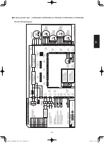
Overall Flow Chart of Defrosting Control
Outdoor heat exchanger temperature sensor
min(C1, C2)
(°C)
Normal heating operation
Has frost adherence been
detected?
Has more than 20 minutes
(heating mask time) elapsed?
Heating operation resumed
Yes (elapsed)
Yes (satisfied)
Have the conditions for ending
defrosting been satisfied?
Heating
operation
continued
Heating
operation
continued
Defrosting
operation
continued
Yes (detected)
Defrosting operations commenced
No
No
No
Frost adherence detection
•
If the following conditions are satisfied during heating operations, it is regarded as “frost adherence is detected”.
•
Frost adherence detection is performed in accordance with the ambient temperature (TO) and the outdoor heat exchanger
temperature sensor min(C1, C2).
•
Frost adherence detection conditions
(a)
(c) Following satisfied condition is detected for accumulation of over 80 minutes.
Following satisfied condition is detected for accumulation of 60 minutes.
Outdoor heat exchanger temperature sensor min(C1, C2) < -3 °C
Outdoor heat exchanger temperature sensor min(C1, C2) < L1
(b) Following satisfied condition is detected for consecutive 1 minutes or more, 2 times.
Outdoor heat exchanger temperature sensor min(C1, C2) < L2
_
Heating Mask Time
This refers to the shortest time that heating operations must be performed without defrosting operations being executed.
The mask time for this model is 20 minutes.
* Defrosting operations will not be commenced until the defrosting mask time has elapsed, even if frost adherence has
been detected.
_
Ending Defrosting
Defrosting operations are ended when the following conditions are satisfied.
•
Ending defrosting conditions
(a)
(b)
(c)
When the temperature of the outdoor heat exchanger temperature sensor (C1) is 10°C or higher.
When the temperature of the outdoor heat exchanger temperature sensor (C1) is 6°C or higher for consecutive
60 seconds.
When a maximum of 15 minutes defrosting time has elapsed.
9) Outdoor Unit Fan Control
The appropriate rotations per minute for the outdoor unit fan are determined in accordance with the ambient
temperature and the frequency of the compressor inverter.
The outdoor unit fan step is controlled between a range of W0 (Step 1) and WF (Step 16).
10) Outdoor Unit's Electrical Expansion Valve Control
The electrical expansion valve controls the amount of refrigerant that is allowed to flow in accordance with the
operation status.
The valve is adjusted in accordance with the discharge temperature (TD), the outdoor heat exchanger
temperature sensor (C1), the suction temperature sensor (TS), and the indoor unit's heat exchanger
temperature sensors (E1 and E2).
(1)
Controlled so that the suction temperature (TS) - indoor heat exchanger temperature minimum (E1 and E2)
is between 0 degree and 2 degrees under normal conditions.
There are cases where the aperture opens wider than normal operation if the discharge temperature increases.
(2)
Cooling Mode
Heating Mode
Controlled so that the suction temperature (TS) - outdoor heat exchanger temperature (C1) is between
0 degree and 2 degrees under normal conditions.
There are cases where the aperture opens wider than normal operation if the discharge temperature increases.
11) Demand Control
* The operational current is restricted to either A% or B% as a general indicator during demand input.
•
•
•
A% and B% can be amended in calibrations of 5% between 70% and 100% with the outdoor unit's
maintenance remote controller.
For details on how to amend the parameters, see the chapter on the outdoor maintenance remote
controller, (refer to the section “6-6. Settings Modes : Setting the Outdoor Unit EEPROM”).
A% value amendments: Parameters are amended with item code “1A” (demand 1).
B% value amendments: Parameters are amended with item code “1B” (demand 2).
There is a demand terminal as normal equipment in the outdoor unit.
Demand control can be selected as the following table.
Input current should be DC24V, 10mA
Connecting wiring must be used “shield wiring”.
Short-circuit
Control (range of operations)
LV3-COM
LV2-COM
LV1-COM
0
0
1
No ristricted
0
0
1
0
0
0
0
0
1
Rated current restricted to A% (A% = 75% at factory shipment)
Rated current restricted to B% (B% = 50% at factory shipment)
Control OFF
SM830276-00_欧州向け R32シングル TD&SM.indb 7
19/02/28 9:01:04
Содержание Elite Big PAC-i S-200PE3E5B
Страница 12: ...MEMO Xi SM830276 00_ R32 TD SM indb 12 19 02 26 15 26 22...
Страница 160: ...1 14 8 MEMO SM830276 00_ R32 TD SM indb 8 2019 02 27 11 55 39...
Страница 176: ...MEMO 2 16 SM830276 00_ R32 TD SM indb 16 19 02 28 13 23 00...
Страница 182: ...MEMO 3 6 SM830276 00_ R32 TD SM indb 6 19 02 26 10 39 17...
Страница 197: ...4 15 4 4 3 Outdoor Unit HIC Board U 200PZH2E8 U 250PZH2E8 ACXA73 3104 SM830276 00_ R32 TD SM indb 15 19 02 28 9 01 10...
Страница 238: ...MEMO 5 38 SM830276 00_ R32 TD SM indb 38 19 02 28 13 29 52...
Страница 316: ...201903 SM830276 00_ R32 TD SM indb 1 19 02 15 8 52 12...


