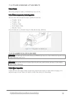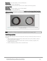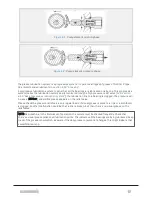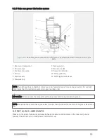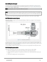
Figure 8.1 :
Pump element, suction phase
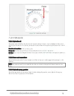
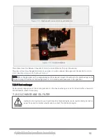
Figure 8.2 :
Pump element, pressure phase
The grease lubrication system is a progressive system. It operates all types of grease of NLGI kl. 2 type.
See recommended lubricants in
A progressive lubrication system, means that all the bearings are lubricated one by one. This progressive
system makes the lubrication system easily monitored trough a high pressure relief valve (nr.9,
8.1.3 "Beka max grease lubrication system"
). If a lubrication line to a bearing is clogged, the pressure will
increase (280 bar) and visible grease appears on the relief valve.
Please check the pressure relief valve on a regular basis. If visual grease is present, a line or a distributor
is clogged. Another malfunction could be that a line is broken, but then there’s no visual grease on the
relief valve.
NOTE: New machine: In the first weeks of operation, the system must be checked frequently. Check that
there’s a visual grease collar on all lubrication points. This indicates all the bearings are being lubricated. Keep
track of the grease consumption. Be aware if the daily grease consumption changes. This might indicate that
something is wrong.
8 LUBRICATION
97
Содержание Dens-X Compactor
Страница 14: ...1 6 DECLARATION OF CONFORMITY 1 GENERAL 14...
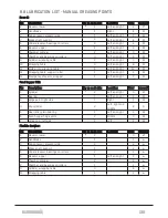
Страница 102: ...8 6 4 Gearbox and gears for hydraulic motors Gear oil Renolin unisyn CLP 220N 8 LUBRICATION 102...
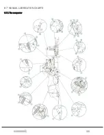
Страница 103: ...8 7 MANUAL LUBRICATION CHARTS 8 7 1 The compactor 8 LUBRICATION 103...
Страница 104: ...8 7 2 Feed hopper F25 8 LUBRICATION 104...
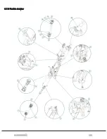
Страница 105: ...8 7 3 Flexible drawbar 8 LUBRICATION 105...
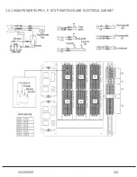
Страница 109: ...10 1 MAIN POWER SUPPLY E STOP SWITCHES AND ELECTRICAL CABINET 10 ELECTRICS 109...
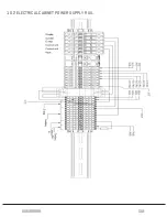
Страница 110: ...10 2 ELECTRICAL CABINET POWER SUPPLY RAIL 10 ELECTRICS 110...
Страница 111: ...10 3 SENSORS AND MANUAL CONTROLS 10 ELECTRICS 111...
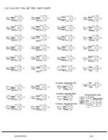
Страница 112: ...10 4 VALVES FAN MOTORS AND PUMPS 10 ELECTRICS 112...
Страница 124: ...10 9 SENSOR OVERVIEW 10 ELECTRICS 124...
Страница 128: ...11 1 1 Complete diagram 11 HYDRAULICS 128...
Страница 129: ...11 1 2 Wrapping table chamber and elevator control 11 HYDRAULICS 129...
Страница 130: ...11 1 3 Plastic tying unit sub conveyor and feed hopper 11 HYDRAULICS 130...
Страница 131: ...11 1 4 Additional feed hopper control for F25 and chamber drive 11 HYDRAULICS 131...
Страница 133: ...11 2 VALVE OVERVIEW 11 2 1 Valve chart for Dens X 11 HYDRAULICS 133...
Страница 137: ...12 6 3 Dimensional sketch F25 operating mode 12 SPECIFICATIONS 137...
Страница 138: ...12 6 4 Dimensional sketch F25 transport mode 12 SPECIFICATIONS 138...
Страница 142: ...M Maintenance 13 69 71 INDEX 142...

