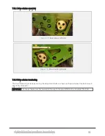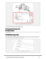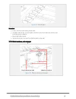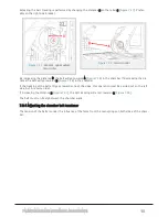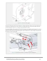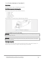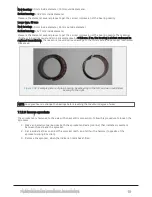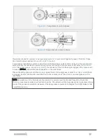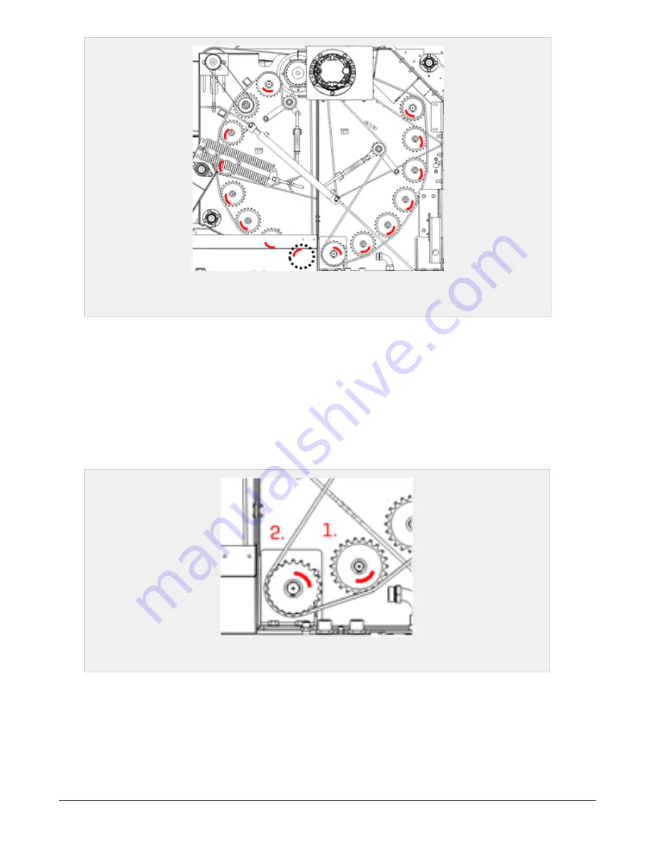
Figure 7.30 :
Check for play in the bushings. Red markings indicate areas on the
bushings.
There are two typical conditions of a worn out bushing, depending on where the bushing is located on the
machine. Read the description and see
.
1. Bale pressure
This is the most typical condition. These bushings are worn the most when the chamber is «full», and the
bale pressure forces the rollers outwards. Thus the most wear on the bushings will be on the outer side.
2. Drive chain
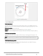
This condition occurs on the bushings that are affected by the drive chain direction. A turning point is
shown in
. The wear is also influenced by the chamber pressure. But not as excessive as for con-
dition 1. Thus the most wear in these conditions are located on the opposite side of the chain contact side.
Figure 7.31 :
Bushings
Inspection
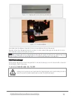
Use a crowbar and inspect each bushing from multiple angles. The worn out areas might be located at dif-
ferent possitions according to how the machine has been used, and which material has been baled.
7.12.2 Permissible wear
Small type, 40 mm
7 MAINTENANCE AND MECHANICAL ADJUSTMENTS
89
Содержание Dens-X Compactor
Страница 14: ...1 6 DECLARATION OF CONFORMITY 1 GENERAL 14...
Страница 102: ...8 6 4 Gearbox and gears for hydraulic motors Gear oil Renolin unisyn CLP 220N 8 LUBRICATION 102...
Страница 103: ...8 7 MANUAL LUBRICATION CHARTS 8 7 1 The compactor 8 LUBRICATION 103...
Страница 104: ...8 7 2 Feed hopper F25 8 LUBRICATION 104...
Страница 105: ...8 7 3 Flexible drawbar 8 LUBRICATION 105...
Страница 109: ...10 1 MAIN POWER SUPPLY E STOP SWITCHES AND ELECTRICAL CABINET 10 ELECTRICS 109...
Страница 110: ...10 2 ELECTRICAL CABINET POWER SUPPLY RAIL 10 ELECTRICS 110...
Страница 111: ...10 3 SENSORS AND MANUAL CONTROLS 10 ELECTRICS 111...
Страница 112: ...10 4 VALVES FAN MOTORS AND PUMPS 10 ELECTRICS 112...
Страница 124: ...10 9 SENSOR OVERVIEW 10 ELECTRICS 124...
Страница 128: ...11 1 1 Complete diagram 11 HYDRAULICS 128...
Страница 129: ...11 1 2 Wrapping table chamber and elevator control 11 HYDRAULICS 129...
Страница 130: ...11 1 3 Plastic tying unit sub conveyor and feed hopper 11 HYDRAULICS 130...
Страница 131: ...11 1 4 Additional feed hopper control for F25 and chamber drive 11 HYDRAULICS 131...
Страница 133: ...11 2 VALVE OVERVIEW 11 2 1 Valve chart for Dens X 11 HYDRAULICS 133...
Страница 137: ...12 6 3 Dimensional sketch F25 operating mode 12 SPECIFICATIONS 137...
Страница 138: ...12 6 4 Dimensional sketch F25 transport mode 12 SPECIFICATIONS 138...
Страница 142: ...M Maintenance 13 69 71 INDEX 142...

