Oracle Sun Fire X4240 Скачать руководство пользователя страница 80

4-18

Sun Fire X4240 Server Service Manual • September 2010
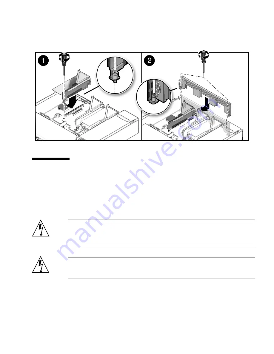
FIGURE 4-9

Installing a PCIe Riser

4.4

Servicing PCIe Cards

The following topics are covered:

Section 4.4.1, “Sun Fire X4240 PCIe Card Guidelines” on page 4-19

Section 4.4.2, “Removing PCIe Cards” on page 4-20

Section 4.4.3, “Installing PCIe Cards” on page 4-22

Caution –

This procedure requires that you handle components that are sensitive to

static discharge. This sensitivity can cause the component to fail. To avoid damage,
ensure that you follow antistatic practices as described in

Section 2.8, “Performing

Electrostatic Discharge and Antistatic Prevention Measures” on page 2-10

.

Caution –

Ensure that all power is removed from the server before removing or

installing expansion cards. You must disconnect the power cables before performing
this procedure.

Содержание Sun Fire X4240

Страница 1: ...Sun Fire X4240 Server Service Manual Part No 820 3835 14 September 2010 Revision A ...

Страница 2: ...ODUIT CONTIENT DES INFORMATIONS CONFIDENTIELLES ET DES SECRETS COMMERCIAUX DE SUN MICROSYSTEMS INC SON UTILISATION SA DIVULGATION ET SA REPRODUCTION SONT INTERDITES SANS L AUTORISATION EXPRESSE ECRITE ET PREALABLE DE SUN MICROSYSTEMS INC Cette distribution peut inclure des éléments développés par des tiers Sun Sun Microsystems le logo Sun Java Solaris et Sun Fire 4140 Sun Fire 4240 and Sun Fire 44...

Страница 3: ...re X4240 Front Panel Features 1 8 1 4 Sun Fire X4240 Rear Panel Features 1 9 1 5 Illustrated Parts Breakdown 1 10 2 Preparing to Service the System 2 1 2 1 Safety Information 2 1 2 2 SSD Minimum Required Firmware 2 2 2 3 Required Tools 2 2 2 4 Obtaining the Chassis Serial Number 2 3 To View Chassis Serial Number 2 3 2 5 Powering Off the Server 2 4 2 5 1 Powering Off the Server Using the Service Pr...

Страница 4: ...e Devices 3 1 3 1 Devices That Are Hot Pluggable or Hot Swappable 3 1 3 1 1 Hot Pluggable Devices 3 1 3 1 2 Hot Swappable Devices 3 2 3 2 Servicing Drives 3 2 3 2 1 Sun Fire X4240 Drive Guidelines 3 2 3 2 2 Sun Fire X4240 SSD Guidelines 3 3 3 2 2 1 SSD Firmware Requirements 3 4 3 2 3 Drive Status LED Reference 3 5 3 2 4 Removing a Hard Drive or SSD 3 5 3 2 5 Installing a Hard Drive or SSD 3 7 3 2 ...

Страница 5: ... DIMM Guidelines 4 4 4 1 2 1 DDR2 DIMM Placement 4 5 4 1 2 2 DDR2 DIMM Fillers 4 6 4 1 2 3 Single Processor Configuration DDR2 DIMM Placement 4 6 4 1 3 Removing DDR2 DIMMs 4 7 4 1 4 Installing DDR2 DIMMs 4 8 4 1 5 Installing Additional DDR2 DIMMs 4 10 4 2 Servicing the Air Duct 4 11 4 2 1 Removing the Air Duct 4 11 4 2 2 Installing the Air Duct 4 13 4 3 Servicing PCIe Risers 4 15 4 3 1 Removing a ...

Страница 6: ...ile 4 35 4 8 Servicing Processors 4 35 4 8 1 Processor Fault Remind Button 4 36 4 8 2 Removing a Processor 4 37 4 8 3 Installing a Processor FRU 4 38 4 8 4 Installing an X option Processor 4 41 4 9 Resetting Passwords and Clearing CMOS NVRAM 4 42 4 9 1 Overview 4 42 4 9 2 Resetting a Service Processor Password From the BIOS Screen 4 42 4 9 3 Resetting CMOS NVRAM Using a Jumper 4 43 4 10 Recovering...

Страница 7: ... 14 5 5 Servicing the Power Distribution Board PDB 5 14 5 5 1 Removing the Power Distribution Board 5 14 5 5 2 Installing the Power Distribution Board 5 15 5 6 Servicing the Power Supply Backplane 5 17 5 6 1 Removing the Power Supply Backplane 5 17 5 6 2 Installing the Power Supply Backplane 5 18 5 7 Servicing the Paddle Card 5 19 5 7 1 Removing the Paddle Card 5 19 5 7 2 Installing the Paddle Car...

Страница 8: ...ST Codes B 1 B 1 Introduction B 1 B 2 How BIOS POST Memory Testing Works B 2 B 3 Redirecting Console Output B 2 B 4 Changing POST Options B 3 B 5 POST Codes B 4 C BIOS Screens C 1 C 1 Configuring BIOS Settings C 1 C 1 1 Using BIOS Menu Items C 1 C 1 2 BIOS Setup Screens Overview C 2 C 2 BIOS Setup Menu Screens C 5 C 2 1 BIOS Main Menu Screens C 5 C 2 2 BIOS Advanced Menu Screens C 6 C 2 3 BIOS PCI...

Страница 9: ...Contents ix Index Index 1 ...

Страница 10: ...x Sun Fire X4240 Server Service Manual September 2010 ...

Страница 11: ...pter Describes Chapter 1 Sun Fire X4240 Server Overview provides an overview of the system including front and rear panel features Contains illustrations showing system components Chapter 2 Preparing to Service the System describes the steps necessary to prepare the system for service Chapter 3 Servicing Customer Replaceable Devices describes the service procedures that can be done while the syste...

Страница 12: ...re the service processor and how to configure the preinstalled Solaris Operating System 820 2394 Sun Fire X4140 X4240 and X4440 Servers Operating System Installation Guide How to install and configure operating systems on the Sun Fire X4140 X4240 and X4440 servers Excludes the preinstalled Solaris Operating System and the Windows operating system 820 2397 Sun Fire X4140 X4240 and X4440 Server Wind...

Страница 13: ...ipment damage To avoid personal injury and equipment damage follow the instructions Sun Function URL Description Documentation http docs sun com You can navigate to the Sun Fire X4240 document page and then download PDF and view HTML documents Includes the LSI card MegaRAID Storage Manager x64 Server Utilities Reference Manual for MSM Support http www sun com support Obtain technical support and d...

Страница 14: ...risk of electric shock and danger to personal health follow the instructions Sun Welcomes Your Comments Sun is interested in improving its documentation and welcomes your comments and suggestions To submit your comments go to http www sun com hwdocs feedback Please include the title and part number of your document with your feedback Example Sun Fire X4240 Server Service Manual part number 820 383...

Страница 15: ...verview on page 1 3 Section 1 3 Sun Fire X4240 Front Panel Features on page 1 8 Section 1 4 Sun Fire X4240 Rear Panel Features on page 1 9 Section 1 5 Illustrated Parts Breakdown on page 1 10 1 1 Product Description The Sun Fire X4240 Server is an enterprise class two socket rackmount x64 system powered by AMD Opteron processors packing high performance and room for growth with six PCIe slots and ...

Страница 16: ...ves Up to 16 SFF SAS 73 GB or 146 GB 2 5 inch form factor drives Support for hardware embedded RAID 0 striping and RAID 1 mirroring Optional RAID Levels 0 1 IE 5 5EE 6 10 50 and 60 Removable media 1 slimline DVD drive supporting CD R W CD R W DVD R W DVD R W USB ports 5 USB 2 0 ports 2 in front 2 in rear plus 1 internal USB port Service ports 1 RJ 45 serial management port SER MGT default connecti...

Страница 17: ...and v3 Remote graphical access remote KVM over Ethernet Remote storage over Ethernet Operating system Solaris 10 Update 6 Solaris 10 OS with specific Sun Fire X4240 Server software components Supports Red Hat Enterprise Linux 4 7 AS 32 bit 64 bit Red Hat Enterprise Linux 5 3 64 bit SUSE Linux Enterprise Server 10 SP2 64 bit VMware ESX 3 0 3 ESX 3 5 ESXi 3 5 Windows Server 2003 x32 SP2 or greater S...

Страница 18: ...power supplies connect directly to the power distribution board Section 5 5 Servicing the Power Distribution Board PDB on page 5 14 Paddle card FRU This board serves as the interconnect between the power distribution board and the fan power boards drives backplane and I O board Section 5 7 Servicing the Paddle Card on page 5 19 Fan power boards 2 FRU These boards carry power to the system fan modu...

Страница 19: ...0 FIGURE 1 1 Cables SAS TABLE 1 3 Sun Fire X4240 Server Cables SAS Cable Connects 1 Drives data cables 2 Between the motherboard or optional HBA PCI Express Card and the drives backplane 2 Motherboard to PDB cable Between the power distribution board and the motherboard 3 Top cover interlock cable To the power distribution board 4 PSU backplane cable To the power supply units ...

Страница 20: ...gend Sun Fire X4240 Server Cables Diskless Configuration Cable Connects 1 Drives data cables 2 Between the motherboard or optional HBA PCI Express Card and the drives backplane 2 Motherboard to PDB cable Between the power distribution board and the motherboard 3 PSU backplane cable To the power supply units 4 Top cover interlock cable To the power distribution board ...

Страница 21: ...ed in TABLE 1 4 TABLE 1 4 Sun Fire X4240 Server Dimensions Dimension Sun Fire X4240 Height 87 85 mm 3 46 inches Width 445 71 mm 17 55 inches includes ears chassis is 425 46 mm 16 75 inches Depth 733 65 mm 28 88 inches includes PSU handle the chassis is 711 25 mm 28 00 inches Weight Maximum 25 6 kg 56 3 pounds ...

Страница 22: ... panel features on the Sun Fire X4240 FIGURE 1 3 Front Panel Features Figure Legend 1 Locator LED Locator button white 5 Power Supply Service Required LED amber 2 Service Action Required LED amber 6 System Overtemperature LED amber 3 Power OK LED green 7 Fan Module Service Required LED amber 4 Power button 8 Drives map ...

Страница 23: ...Ie slots see Section 4 3 Servicing PCIe Risers on page 4 15 FIGURE 1 4 Rear Panel Features Figure Legend 1 PSU 1 9 Rear Panel System Status LEDs Locator LED Locator button white Service Action Required LED amber Power OK LED green 2 PSU 0 10 Serial Management Port 3 PCIe 3 11 Network Management Port 4 PCIe 0 NMI button Behind panel not shown 5 PCIe 4 Reset Button Behind panel not shown 6 PCIe 1 12...

Страница 24: ...oded views of system components Use these illustrations and the accompanying tables to identify parts in your system FIGURE 1 5 I O Components Sun Fire X4240 Figure Legend 1 Top Cover 5 Drives 2 Hard Disk Backplane 6 DVD USB Module 3 Hard Disk Cage 7 Left Control Panel Light Pipe Assembly 4 Left Control Panel Light Pipe Assembly ...

Страница 25: ...rver Overview 1 11 FIGURE 1 6 Power Distribution Fan Module Components Sun Fire X4240 Figure Legend 1 Paddle Card 5 Fan Modules 2 Power Distribution Board Bus Bar Assembly 6 Fan Boards 3 Paddle Card 7 Air Baffle 4 Power Supplies ...

Страница 26: ...ontaminant build up It is recommended that systems be opened and checked approximately every six months or more often in dirty operating environments Check system heat sinks fans and air openings If necessary clean systems by brushing or blowing contaminants or carefully vacuuming contaminants from the system ...

Страница 27: ...on 2 6 Extending the Server to the Maintenance Position on page 2 6 Section 2 7 Removing a Server From the Rack on page 2 8 Section 2 8 Performing Electrostatic Discharge and Antistatic Prevention Measures on page 2 10 Section 2 9 Removing the Top Cover on page 2 12 2 1 Safety Information This section describes important safety information that you need to know prior to removing or installing part...

Страница 28: ...e match the voltage and frequency inscribed on the equipment s electrical rating label Follow the electrostatic discharge safety practices as described in this chapter 2 2 SSD Minimum Required Firmware BIOS ILOM Firmware BIOS 0ABMN064 ILOM 3 0 3 37 Adaptec Firmware Adaptec FW 16732 LSI FW 1 27 02 MPTBIOS 6 26 00 Backplane Firmware Backplane FW 5 02 14 LSI SAS expander SSD firmware Intel SSD FW 845...

Страница 29: ...l is on the top of the server FIGURE 2 1 Chassis Serial Number Label To View Chassis Serial Number To view information about a system component you need the Read Only o role enabled 1 Log in to the ILOM CLI 2 At the prompt type cd SYS SYS cd MB SYS MB show chassis_serial_number type SYS MB Properties chassis_serial_number 0811QAD01C type Motherboard For more information see Sun Integrated Lights O...

Страница 30: ...pointed object to press and release the Power button on the front panel Pressing the power button causes Advanced Configuration and Power Interface ACPI enabled operating systems to perform an orderly shutdown of the operating system Servers not running ACPI enabled operating systems will shut down to standby power mode immediately Emergency shutdown Press and hold the Power button for at least fo...

Страница 31: ... to the Solaris OS documentation for additional information 1 Log in as a superuser or equivalent Depending on the type of problem you might want to view server status or log files or run diagnostics before you shut down the server 2 Notify affected users 3 Save any open files and quit all running programs Refer to your application documentation for specific information 4 Shut down all logical dom...

Страница 32: ...ice processor SP prompt to locate the system that requires maintenance After you have located the server press the Locator LED Locator button to turn it off 2 Verify that no cables will be damaged or will interfere when the server is extended Although the cable management arm CMA that is supplied with the server is hinged to accommodate extending the server you should ensure that all cables and co...

Страница 33: ...Chapter 2 Preparing to Service the System 2 7 FIGURE 2 3 Slide Release Latches 5 While squeezing the slide release latches slowly pull the server forward until the slide rails latch ...

Страница 34: ...ismount and carry the chassis To remove a server from the rack 1 Disconnect all cables and power cords from the server 2 Extend the cabinet extender arm for safety if present 3 Extend the server to the maintenance position See Section 2 6 Extending the Server to the Maintenance Position on page 2 6 4 Press the metal lever that is located on the inner side of the rail to disconnect the cable manage...

Страница 35: ...r and Cable Management Arm Caution If necessary use two people to dismount and carry the chassis 5 From the front of the server pull the release tabs forward and pull the server forward until it is free of the rack rails FIGURE 2 5 A release tab is located on each rail ...

Страница 36: ...c discharge ESD sensitive devices such as the motherboards PCI cards hard drives SSDs and memory cards require special handling Caution Circuit boards hard drives and SSDs contain electronic components that are extremely sensitive to static electricity Ordinary amounts of static electricity from clothing or the work environment can destroy the components located on these boards Do not touch the co...

Страница 37: ...X4240 However antistatic wrist straps are still included with options 2 8 1 2 Using an Antistatic Mat Place antistatic sensitive components such as motherboards memory and other PCBs on an antistatic mat 2 8 2 Antistatic Handling Procedure 1 Prepare an antistatic surface to set parts on during the removal installation or replacement process Place antistatic sensitive components such as the printed...

Страница 38: ...tton and slide the top cover to the rear about a half inch 12 7 mm 2 3 Lift up and remove the top cover 3 Caution If the top cover is removed before the server is powered off the server will immediately go into Standby mode Note System cooling might be affected by dust and contaminant buildup It is recommended that systems be opened and checked approximately every six months or more often in dirty...

Страница 39: ...Chapter 2 Preparing to Service the System 2 13 FIGURE 2 6 Removing the Top Cover ...

Страница 40: ...2 14 Sun Fire X4240 Server Service Manual September 2010 ...

Страница 41: ... on page 3 15 CRU Section 3 5 Servicing the DVD USB Module on page 3 20 CRU 3 1 Devices That Are Hot Pluggable or Hot Swappable 3 1 1 Hot Pluggable Devices Hot pluggable devices can be removed and installed while the server is running but you must perform administrative tasks before or after installing the hardware for example mounting a drive In the Sun Fire X4240 only drives are hot pluggable To...

Страница 42: ...e depending on how they are configured See Section 3 2 Servicing Drives on page 3 2 3 2 Servicing Drives The following topics are covered Section 3 2 1 Sun Fire X4240 Drive Guidelines on page 3 2 Section 3 2 2 Sun Fire X4240 SSD Guidelines on page 3 3 Section 3 2 3 Drive Status LED Reference on page 3 5 Section 3 2 4 Removing a Hard Drive or SSD on page 3 5 Section 3 2 5 Installing a Hard Drive or...

Страница 43: ...erver with 8 drives The Sun Fire X4x40 servers support solid state drives SSDs under the following conditions Sun Fire X4240 with on board controller No SSDs can be installed Sun Fire X4240 with HBA One to 8 SSDs can be installed into the system for the X4240 TABLE 3 1 Physical Drive Locations HD3 HD7 N A HD12 HD15 HD2 HD6 N A HD11 HD14 HD1 HD5 HD9 DVD drive HD0 HD4 HD8 HD10 HD13 TABLE 3 1 Physica...

Страница 44: ...e Requirements When replacing or installing a SSD to be included in a RAID configuration in the Sun Fire X4240 system make sure that the firmware on the newly installed SSD is the same as the firmware that is installed on the other SSDs in the RAID volume Minimum required firmware BIOS ILOM Firmware BIOS 0ABMN064 ILOM 3 0 3 37 Adaptec Firmware Adaptec FW 16732 LSI FW 1 27 02 MPTBIOS 6 26 00 Backpl...

Страница 45: ...ove it To remove a drive from a Sun Fire X4240 1 Identify the drive you wish to remove The amber Service Required LED might be lit For specific drive locations see Section 3 2 1 Sun Fire X4240 Drive Guidelines on page 3 2 Figure Legend Legend LED Symbol Color Lights when 1 OK to Remove Blue A drive can be removed safely during a hot plug operation Note The blue OK to Remove LED requires OS support...

Страница 46: ...ng HBA documents if your system uses RAID For Sun StorageTek Sun StorageTek RAID Manager Software User s Guide For LSI MegaRAID Storage Manager MSM Sun LSI 106x RAID User s Guide or x64 Server Utilities Reference Manual b Wait until the blue OK to Remove LED becomes lit FIGURE 3 2 before you physically uninstall the drive from the chassis The blue LED indicates that the drive is unconfigured and c...

Страница 47: ...all a drive into the drive slot and then configure that drive to the server Caution Before inserting a replacement drive wait 15 seconds and verify that your monitoring or administration application has detected the missing or failed drive To install a drive into a Sun Fire X4240 1 If necessary remove the drive fillers from the chassis The Sun Fire X4240 might have as many as eight drive fillers c...

Страница 48: ...Slide the drive into the drive slot until it is fully seated FIGURE 3 4 FIGURE 3 4 Installing a Drive 4 Close the latch to lock the drive in place 5 Do one of the following If you have hot plugged the drive Configure the drive See one of the following HBA documents For Sun StorageTek Sun StorageTek RAID Manager Software User s Guide For LSI MegaRAID Storage Manager MSM Sun LSI 106x RAID User s Gui...

Страница 49: ...r out of the chassis FIGURE 3 5 FIGURE 3 5 Drive Filler 3 3 Servicing Fan Modules The following topics are covered Section 3 3 1 About Sun Fire X4240 Fans on page 3 10 Section 3 3 2 Fan Module LED Reference on page 3 10 Section 3 3 3 Detecting Fan Module Failure on page 3 11 Section 3 3 4 Removing a Fan Module on page 3 12 Section 3 3 5 Installing a Fan Module on page 3 13 Note CRU This customer r...

Страница 50: ...d installed while the server is running without affecting the rest of the server s capabilities 3 3 2 Fan Module LED Reference Each fan module contains LEDs that are visible when you open the fan tray access door TABLE 3 4 describes fan tray module LEDs and their functions FIGURE 3 6 shows the fan module locations TABLE 3 4 Fan Module Status LEDs LED Color Lights when Power OK Green The system is ...

Страница 51: ...the server Fan Fault LED on or adjacent to the faulty fan module If an overtemperature conditions occurs the front panel processor overtemperature LED becomes lit and a message is displayed on the console and logged by the iLOM The system Overtemp LED might be lit if a fan fault causes an increase in system operating temperature See Chapter 1 Section 1 3 Sun Fire X4240 Front Panel Features on page...

Страница 52: ... the Maintenance Position on page 2 6 2 Unlatch the fan module door Pull the release tabs back to release the door Open the top cover toward the rear of the server Note Close the top cover door immediately after replacing the fan to maintain airflow in the server Leaving the door open for more than 60 seconds while the server is running might cause the server to overheat and shut down 3 Identify t...

Страница 53: ... service any other components in the fan compartment unless the system is shut down and the power cords are removed FIGURE 3 8 Removing a Fan Module 3 3 5 Installing a Fan Module 1 With the top cover door open install the replacement fan module into the server FIGURE 3 9 The fan modules are keyed to ensure that they are installed in the correct orientation ...

Страница 54: ... Fan OK LED is lit and that the Fan Fault LED on the replaced fan module is not lit 4 Close the top cover door 5 Verify that the Top Fan LED Service Required LEDs and the Locator LED Locator button are not lit See Section 1 2 Sun Fire X4240 Server Chassis Overview on page 1 3 for more information about identifying and interpreting front and back panel LEDs ...

Страница 55: ...pply Failure on page 3 15 Section 3 4 2 Power Supply LED Reference on page 3 15 Section 3 4 3 Removing a Power Supply on page 3 16 Section 3 4 4 Installing a Power Supply on page 3 18 Note CRU This customer replaceable unit can be replaced by anyone 3 4 1 Detecting Power Supply Failure The following LEDs are lit when a power supply fault is detected Front and rear Service Required LEDs Rear PS Fai...

Страница 56: ...access to the rear of the server where the faulty power supply is located 3 Release the cable management arm CMA FIGURE 3 11 The CMA is located at the rear of the server rack a Press and hold the tab Figure Legend Legend LED Symbol Color Lights when 1 OK to Remove Blue A power supply can be removed safely during a hot swap operation 2 Service Required Amber The power supply is faulty The front and...

Страница 57: ...ent arm out of the way so that you can access the power supply FIGURE 3 11 Releasing the Cable Management Arm 4 Disconnect the power cord from the faulty power supply 5 Grasp the power supply handle and press the release latch FIGURE 3 12 6 Pull the power supply out of the chassis ...

Страница 58: ...d or cords to the power supply or supplies Verify that the AC Present LED is lit 4 Close the CMA inserting the end of the CMA into the rear left rail bracket FIGURE 3 11 5 Verify that the following LEDs are not lit Failure LED on the replaced power supply Service Required LED Front Service Required LED Rear Service Required LED Note See Section 1 3 Sun Fire X4240 Front Panel Features on page 1 8 a...

Страница 59: ...mand FIGURE 3 13 Installing a Power Supply 3 5 Servicing the DVD USB Module The DVD drive and front USB board are mounted in a removable module that is accessible from the front panel of the system The DVD USB module must be removed from the drive cage to service the drives backplane Note CRU This customer replaceable unit can be replaced by anyone ...

Страница 60: ...rver on page 2 4 c Attach an antistatic wrist strap See Section 2 8 Performing Electrostatic Discharge and Antistatic Prevention Measures on page 2 10 3 Remove the Sun Fire X4240 HDD13 drive See Section 1 2 Sun Fire X4240 Server Chassis Overview on page 1 3 for drive locations 4 Release the DVD USB module from the drives backplane FIGURE 3 14 Use the finger indent in the drive bay below the DVD US...

Страница 61: ...VD USB Module 3 5 2 Installing the DVD USB Module 1 Slide the DVD USB module into the front of the chassis until it seats FIGURE 3 15 2 Install the drive you removed during the DVD USB module removal procedure 3 Power on the server See Section 6 4 Powering On the Server on page 6 5 ...

Страница 62: ...3 22 Sun Fire X4240 Server Service Manual September 2010 FIGURE 3 15 Installing the DVD USB Module ...

Страница 63: ...age 4 15 CRU Section 4 4 Servicing PCIe Cards on page 4 18 CRU Section 4 5 Servicing the Battery on page 4 24 CRU Section 4 6 Servicing the Motherboard Assembly on page 4 27 FRU Section 4 7 Servicetool FRU Update Procedures on page 4 32 Section 4 8 Servicing Processors on page 4 35 FRU Section 4 9 Resetting Passwords and Clearing CMOS NVRAM on page 4 42 Section 4 10 Recovering From Corrupt Service...

Страница 64: ...agnostics Guide for additional DIMM troubleshooting information Note CRU This customer replaceable unit can be replaced by anyone Caution This procedure requires that you handle components that are sensitive to static discharge This sensitivity can cause the component to fail To avoid damage ensure that you follow antistatic practices as described in Section 2 8 1 Electrostatic Discharge Safety Me...

Страница 65: ...moving the Top Cover on page 2 12 2 Press and hold the Remind button to identify which DDR2 DIMM is faulty FIGURE 4 1 3 Note the location of faulty DDR2 DIMMs Faulty DDR2 DIMMs are identified with a corresponding amber LED on the motherboard 4 Ensure that all DDR2 DIMMs are seated correctly in their slots If re seating the DDR2 DIMM does not fix the problem remove and replace the faulty DDR2 DIMM ...

Страница 66: ... your server There are 16 slots in P0 and P1 that hold industry standard DDR2 DIMM modules All DDR2 DIMMs must be the same density same type The Sun Fire X4240 supports the following configurations From 2 DDR2 DIMMs minimum configuration To 16 DDR2 DIMMs fully populated configuration In increments of 2 DDR2 DIMMs At minimum Branch 0 must be fully populated with two DDR2 DIMMs of the same density s...

Страница 67: ...ics Guide for additional DDR2 DIMM information The DIMM population rules for the server are as follows Each processor can support a maximum of eight DIMMs The DIMM slots are paired and the DIMMs must be installed in pairs 0 1 2 3 4 5 and 6 7 The memory sockets are colored black or white to indicate which slots are paired by matching colors DIMMs are populated starting from the outside away from th...

Страница 68: ...R2 DIMM Fillers DDR2 DIMM fillers are installed in all unoccupied DIMM sockets All sockets must be occupied by either a filler or a DDR2 DIMM When DDR2 DIMMS are added remove the fillers When DDR2 DIMMS are removed add extra fillers Always place fillers in empty sockets FIGURE 4 3 Fillers for DDR2 DIMM Slots 4 1 2 3 Single Processor Configuration DDR2 DIMM Placement If a one processor configuratio...

Страница 69: ...he Maintenance Position on page 2 6 d Attach an antistatic wrist strap See Section 2 8 Performing Electrostatic Discharge and Antistatic Prevention Measures on page 2 10 e Remove the top cover See Section 2 9 Removing the Top Cover on page 2 12 3 Lift up the air duct FIGURE 4 4 1 4 If you are replacing a faulty DDR2 DIMM press the Remind button on the motherboard to locate the DDR2 DIMMS that you ...

Страница 70: ...age to the DDR2 DIMMs might occur You must disconnect all power cables from the system before performing this procedure Tip See Section 4 1 2 DDR2 DIMM Guidelines on page 4 4 for information about configuring the DDR2 DIMMs 1 Unpackage the replacement DDR2 DIMMs and place them on an antistatic mat 2 Ensure that the ejector tabs are in the open position 3 Line up the replacement DDR2 DIMM with the ...

Страница 71: ...to the down position 7 Install the top cover See Section 6 1 Installing the Top Cover on page 6 2 8 Slide the server into the rack See Section 6 3 Returning the Server to the Normal Rack Position on page 6 4 9 Reconnect the power cord or cords to the power supply or supplies Verify that the AC Present LED is lit See Section 6 4 Powering On the Server on page 6 5 10 Power on the server See Section ...

Страница 72: ... connector until the ejector tabs lock the DDR2 DIMM in place If the DDR2 DIMM does not easily seat into the connector verify that the orientation of the DDR2 DIMM is as shown in FIGURE 4 4 If the orientation is reversed damage to the DDR2 DIMM might occur 6 Repeat Step 2 through Step 5 until all DDR2 DIMMs are installed 7 Replace the air duct to the down position 8 Install the top cover See Secti...

Страница 73: ... server See Section 2 5 Powering Off the Server on page 2 4 b Disconnect the power cord or cords from the power supply or supplies See Section 2 5 Powering Off the Server on page 2 4 c Slide the server out of the rack See Section 2 6 Extending the Server to the Maintenance Position on page 2 6 d Attach an antistatic wrist strap See Section 2 8 Performing Electrostatic Discharge and Antistatic Prev...

Страница 74: ...g the Air Duct 4 2 2 Installing the Air Duct Caution When the server is in operation ensure that the air duct is correctly installed to prevent the system from overheating 1 Install the air duct into the chassis as shown in FIGURE 4 7 Ensure that the air duct is aligned and fully seated in the chassis 2 Move the air duct towards the front ...

Страница 75: ...ll the top cover See Section 6 1 Installing the Top Cover on page 6 2 b Slide the server into the the rack See Section 6 3 Returning the Server to the Normal Rack Position on page 6 4 c Reconnect the power cord or cords to the power supply or supplies Verify that the AC Present LED is lit See Section 6 4 Powering On the Server on page 6 5 d Power on the server See Section 6 4 Powering On the Serve...

Страница 76: ...4 14 Sun Fire X4240 Server Service Manual September 2010 FIGURE 4 7 Installing the Air Duct ...

Страница 77: ...s sensitivity can cause the component to fail To avoid damage ensure that you follow antistatic practices as described in Section 2 8 1 Electrostatic Discharge Safety Measures on page 2 10 4 3 1 Removing a PCIe Riser Caution Ensure that all power is removed from the server before removing or installing risers You must disconnect the power cables before performing this procedure 1 Prepare the serve...

Страница 78: ...CIe card locate its position in the system 3 Disconnect any data cables connected to the cards on the PCIe riser being removed Label the cables to ensure proper connection later 4 Remove the rear panel PCI cross beam FIGURE 4 8 1 a Loosen the two captive Phillips screws on the end of the PCI cross beam b Lift the PCI cross beam up and back to remove it from the chassis 5 Loosen the captive retaini...

Страница 79: ... panel PCI cross beam 2 a Slide the cross beam down over the PCIe risers b Secure the PCI cross beam with two captive Phillips screws 5 Return the server to operation a Install the top cover See Section 6 1 Installing the Top Cover on page 6 2 b Connect any data cables to the PCIe card Route data cables through the cable management arm c Slide the server into the rack See Section 6 3 Returning the...

Страница 80: ...page 4 22 Caution This procedure requires that you handle components that are sensitive to static discharge This sensitivity can cause the component to fail To avoid damage ensure that you follow antistatic practices as described in Section 2 8 Performing Electrostatic Discharge and Antistatic Prevention Measures on page 2 10 Caution Ensure that all power is removed from the server before removing...

Страница 81: ...or size PCIe cards with x4 x8 or x16 mechanical finger pins will fit in any riser slot but will operate at the electrical lane width of the slot Note The SGXPCIESAS R INT Z HBA should be installed in slot 0 to avoid system overheating Make sure that the firmware is at SW 3 1 or later when installing the HBA in Slot 0 FIGURE 4 10 Identifying PCIe Cards TABLE 4 1 Sun Fire X4240 Riser Guidelines Rise...

Страница 82: ...rostatic Discharge and Antistatic Prevention Measures on page 2 10 e Remove the top cover See Section 2 9 Removing the Top Cover on page 2 12 2 Locate the PCIe card that you want to remove and note its corresponding riser board See Section 1 4 Sun Fire X4240 Rear Panel Features on page 1 9 for more information about PCIe slots and their locations 3 If necessary make a note of where the PCIe cards ...

Страница 83: ...Chapter 4 Servicing Motherboard Components 4 21 FIGURE 4 11 Removing a PCIe Card ...

Страница 84: ...tended time inspect the slot for particles Clean the slot with filtered compressed air as required 6 Remove the PCI filler panel PCIe filler panels are located in the motherboard rear panel 7 Insert the PCIe card into the correct slot on the riser board FIGURE 4 12 8 Replace the riser board a Slide the riser back until it seats in its slot in the rear panel b Tighten the captive No 2 Phillips scre...

Страница 85: ...Chapter 4 Servicing Motherboard Components 4 23 13 Power on the server See Section 6 4 Powering On the Server on page 6 5 FIGURE 4 12 Installing a PCIe Card ...

Страница 86: ... when the server is powered off and a time server is unavailable If the server fails to maintain the proper time when powered off and not connected to a network replace the battery FIGURE 4 13 You need a small No 1 flat blade non metallic screwdriver or equivalent Caution Ensure that all power is removed from the server before removing or installing the battery You must disconnect the power cables...

Страница 87: ...the Server on page 2 4 b Disconnect the power cord or cords from the power supply or supplies See Section 2 5 Powering Off the Server on page 2 4 c Slide the server out of the rack See Section 2 6 Extending the Server to the Maintenance Position on page 2 6 d Attach an antistatic wrist strap See Section 2 8 Performing Electrostatic Discharge and Antistatic Prevention Measures on page 2 10 ...

Страница 88: ...therboard Install the positive side facing upward away from the motherboard 3 Install PCIe riser 0 with any associated cards See Section 4 3 2 Installing a PCIe Riser on page 4 17 4 Return the server to operation a Install the top cover See Section 6 1 Installing the Top Cover on page 6 2 b Slide the server into the the rack See Section 6 3 Returning the Server to the Normal Rack Position on page ...

Страница 89: ...ion Ensure that all power is removed from the server before removing or installing the motherboard assembly You must disconnect the power cables from the system before performing this procedure Caution This procedure requires that you handle components that are sensitive to electrostatic discharge This discharge can cause server components to fail To avoid damage ensure that you follow the antista...

Страница 90: ...isers See Section 4 3 1 Removing a PCIe Riser on page 4 15 Note the location of expansion cards in the PCIe risers 4 Disconnect the power distribution board ribbon cable FIGURE 4 14 1 See Section 5 8 3 Removing a PDB Cable on page 5 27 5 Disconnect the drive data cables See Section 1 2 2 System Cables on page 1 5 Caution The drive data cables are delicate Ensure that they are safely out of the way...

Страница 91: ...arge Static discharges can cause component failures To avoid damage ensure that you follow antistatic practices as described in Section 2 8 Performing Electrostatic Discharge and Antistatic Prevention Measures on page 2 10 1 Power off the server See Section 2 5 Powering Off the Server on page 2 4 2 Attach an antistatic wrist strap See Section 2 8 Performing Electrostatic Discharge and Antistatic P...

Страница 92: ...table to 7 inch pounds 0 8 newton meters with a No 2 Phillips screwdriver 7 Fasten the captive screw at the front of the motherboard 3 8 Carefully connect the power distribution board ribbon cable to the motherboard 3 Make sure it is seated properly See Section 5 8 4 Installing a PDB Cable on page 5 28 9 Connect the two drive data cables See Section 1 2 2 System Cables on page 1 5 Be careful when ...

Страница 93: ...l the server into the rack See Section 6 2 Reinstalling the Server in the Rack on page 6 3 c Reconnect the power cord or cords to the power supply or supplies Verify that the AC Present LED is lit See Section 6 4 Powering On the Server on page 6 5 d Power on the server See Section 6 4 Powering On the Server on page 6 5 FIGURE 4 15 Installing the Motherboard Assembly ...

Страница 94: ...he SunService account is for the use of Sun service representatives only Do not use the SunService account unless you are instructed to do so in a procedure developed by Sun Microsystems Note If your system is running ILOM 3 x then you must re enable your SunService account Note Before beginning these procedures obtain Service Escalation passwords from the Customer Support Center 4 7 1 Updating FR...

Страница 95: ...t the service processor for to complete this process Allow the service processor to fully boot DO NOT UNPLUG THE SYSTEM WHILE THE SERVICE PROCESSOR IS BOOTING Would you like to reboot the service processor now y n y The system is going down NOW Sending SIGTERM to all processes Option Description board_replaced BOARD Update FRU information for BOARD after it has been replaced BOARD represents one o...

Страница 96: ...t mb write_cmm_product_area dev shm product info 6 View the file to ensure that the product data has been updated in the motherboard FRUID PROM frutool r mb hexdump C egrep 000004 00000400 00 00 00 00 00 00 00 00 00 00 00 00 00 a4 70 72 pr 00000410 6f 64 75 63 74 20 70 61 72 74 5f 6e 75 6d 62 65 oduct part_numbe 00000420 72 20 35 39 34 2d 35 31 33 33 2d 30 33 0a 70 72 r 594 5133 03 pr 00000430 6f ...

Страница 97: ...oard by issuing this command frutool t mb write_cmm_product_area dev shm product info 4 Read this file to ensure the changes have been made successfully frutool t mb read_cmm_product_area 5 Remove the file you created in the first step of this procedure rm dev shm product info 6 Reboot the SP A reboot enables the SP to re read the FRUID data 4 8 Servicing Processors The following topics are covere...

Страница 98: ...of the server and processors 4 8 1 Processor Fault Remind Button If you are replacing a faulty processor press the Remind button on the motherboard to locate the processor that you want to replace FIGURE 4 16 The faulty processor LED flashes when the Fault Remind button is pressed and held All faulty processors are indicated with an amber LED so that you can install the replacement processor in th...

Страница 99: ...e Position on page 2 6 d Attach an antistatic wrist strap See Section 2 8 Performing Electrostatic Discharge and Antistatic Prevention Measures on page 2 10 e Remove the top cover See Section 2 9 Removing the Top Cover on page 2 12 2 Identify which processor to remove FIGURE 4 18 1 Processor 0 is closest to the PSU bay processor 1 is furthest from the PSU bay 3 Unscrew the two heatsink screws FIGU...

Страница 100: ... FRU 1 Prepare the server for service a Power off the server See Section 2 5 Powering Off the Server on page 2 4 b Disconnect the power cord or cords from the power supply or supplies See Section 2 5 Powering Off the Server on page 2 4 c Slide the server out of the rack See Section 2 6 Extending the Server to the Maintenance Position on page 2 6 ...

Страница 101: ...aterial from the heatsink and processor using the supplied alcohol wipe 5 Set the heat sink aside 6 Place the new processor in the socket Make sure the orientation is correct 7 Engage the lever by rotating downward and pressing it into the catch FIGURE 4 18 Installing a Processor 8 Using the supplied grease syringe empty the syringe on to the processor in a star shaped pattern FIGURE 4 19 9 Orient...

Страница 102: ...into the rack See Section 6 3 Returning the Server to the Normal Rack Position on page 6 4 c Reconnect the power cord or cords to the power supply or supplies Verify that the AC Present LED is lit See Section 6 4 Powering On the Server on page 6 5 d Power on the server See Section 6 4 Powering On the Server on page 6 5 FIGURE 4 19 Installing a Processor ...

Страница 103: ... top cover See Section 2 9 Removing the Top Cover on page 2 12 2 Remove the shipping cover from socket 3 Clean the top of the processor with the provided alcohol wipe 4 Place the processor in the socket with the correct orientation 5 Engage the lever by rotating downward and pressing into the catch 6 Remove the plastic protective cover from heatsink Be careful not to disturb or touch the pre insta...

Страница 104: ...Jumper on page 4 43 4 9 1 Overview Clearing CMOS settings resets the BIOS settings including the BIOS password You can reset a password from the BIOS screen or with a jumper You can also clear the CMOS NVRAM and BIOS password by changing jumpers as listed in TABLE 4 2 4 9 2 Resetting a Service Processor Password From the BIOS Screen To reset a password for the Service Processor access the BIOS Sec...

Страница 105: ...wering Off the Server on page 2 4 c Slide the server out of the rack See Section 2 6 Extending the Server to the Maintenance Position on page 2 6 d Attach an antistatic wrist strap See Section 2 8 Performing Electrostatic Discharge and Antistatic Prevention Measures on page 2 10 e Remove the top cover See Section 2 9 Removing the Top Cover on page 2 12 2 Locate the jumper header J1602 Access the J...

Страница 106: ...mes corrupted you can reinstall the default SP software image from the Tools and Drivers CD You need The Tools and Drivers CD A bootable USB flash device A jumper cap The server has a jumper cap installed on the motherboard next to the AST 2000 chip 4 10 1 Reinstalling The Default SP Software Image From The Tools And Drivers CD This emergency flash recovery procedure returns the SP to a default co...

Страница 107: ... 2 Insert the bootable flash drive into the USB port a Press F8 to get a list of the boot devices b Choose the USB flash boot device or a Press F2 to enter the BIOS setup screen b Choose the USB flash device as the first boot device c Save and exit FIGURE 4 20 Internal USB Port ...

Страница 108: ...t a complete option listing 4 After a successful flash perform an AC power cycle or reset the SP using the following command socflash r Note Using r resetting the SP hardware can cause the VGA display to become disrupted Note The BIOS is not upgraded by this emergency recovery procedure Perform a 2nd ILOM based flash upgrade to update the BIOS version Note This emergency flash recovery procedure r...

Страница 109: ...ter 4 Servicing Motherboard Components 4 47 a BMC Firmware Revision is correct on the Main page b Status of BMC is working in Advanced IPMI 2 0 Configuration page 10 Exit BIOS and start the operating system ...

Страница 110: ...sest to NET0 It can be pushed by sticking a paper clip or similar object through the hole provided on the rear of the chassis 4 11 2 NMI Dump Switch The NMI button is the center button of the row of 3 hidden recessed buttons on the back of the motherboard located between the NET MGT and NET0 connectors The button for this switch can be pushed by sticking a paper clip or similar object through the ...

Страница 111: ... Hard Drive Backplane on page 5 10 FRU Section 5 4 Servicing the Front Control Panel Light Pipe Assembly on page 5 12 FRU Section 5 5 Servicing the Power Distribution Board PDB on page 5 14 FRU Section 5 6 Servicing the Power Supply Backplane on page 5 17 FRU Section 5 7 Servicing the Paddle Card on page 5 19 FRU Section 5 8 Servicing Cables on page 5 21 FRU Caution Never attempt to run the server...

Страница 112: ... 1 Prepare the server for service a Power off the server See Section 2 5 Powering Off the Server on page 2 4 b Disconnect the power cord or cords from the power supply or supplies See Section 2 5 Powering Off the Server on page 2 4 c Slide the server out of the rack See Section 2 6 Extending the Server to the Maintenance Position on page 2 6 Note If you are removing the fan power boards to access ...

Страница 113: ...ove the defective fan power board See Section 3 3 4 Removing a Fan Module on page 3 12 3 Remove the Phillips screw that secures the fan power board to the chassis FIGURE 5 1 4 Slide the fan power board to the left to disengage it from the paddle card 5 Remove the fan power board from the system and place it on an antistatic mat FIGURE 5 1 Removing the Fan Power Board ...

Страница 114: ...s mushroom standoffs in the chassis floor and slide the board to the right into the Paddle card FIGURE 5 2 2 Secure the board to the chassis with a Phillips screw 3 Reinstall the fan modules See Section 3 3 5 Installing a Fan Module on page 3 13 FIGURE 5 2 Installing a Fan Power Board 4 Return the server to operation ...

Страница 115: ...You must remove the drives cage to access the following components Drives backplane Front control panel light pipe assemblies Note FRU This field replaceable unit should be replaced only by qualified service technicians Contact your Sun Service representative for assistance Caution Ensure that all power is removed from the server before removing or installing the drives cage You must disconnect th...

Страница 116: ...l the drives in the correct locations when reassembling the system 3 If you are servicing the drives backplane remove the DVD USB module See Section 3 5 1 Removing the DVD USB Module on page 3 20 4 Remove the fan modules See Section 3 3 4 Removing a Fan Module on page 3 12 5 Remove the fan power boards See Section 5 1 1 Removing a Fan Power Board on page 5 2 6 Remove the No 2 Phillips screws secur...

Страница 117: ...e 2 Position the hard drive cage in the chassis over its standoffs FIGURE 5 4 1 3 Slide the hard drive cage back until the hard drive backplane engages with the paddle card connector FIGURE 5 4 2 4 Replace the No 2 Phillips screws securing the hard drive cage to the chassis FIGURE 5 4 3 Two screws secure the disk cage to each side of the chassis 5 Install the fan power boards See Section 5 1 2 Ins...

Страница 118: ...tion 3 3 5 Installing a Fan Module on page 3 13 FIGURE 5 4 Installing the Hard Drive Cage 7 Install the top cover See Section 6 1 Installing the Top Cover on page 6 2 8 Install the server into the rack See Section 6 2 Reinstalling the Server in the Rack on page 6 3 9 Install the hard drives ...

Страница 119: ...age 3 7 10 Install the DVD USB module See Section 3 5 2 Installing the DVD USB Module on page 3 21 11 Return the server to operation a Reconnect the power cord or cords to the power supply or supplies Verify that the AC Present LED is lit See Section 6 4 Powering On the Server on page 6 5 b Press the power button to power on the server See Section 6 4 Powering On the Server on page 6 5 ...

Страница 120: ...s Contact your Sun Service representative for assistance 5 3 1 Removing the Hard Drive Backplane 1 Remove the DVD USB drive See Section 3 5 1 Removing the DVD USB Module on page 3 20 2 Remove the four No 2 Phillips screws securing the backplane to the hard drive cage FIGURE 5 5 3 Remove the hard drive cage See Section 5 2 1 Removing the Drives Cage on page 5 5 4 Slide the backplane down and off th...

Страница 121: ...e retention hooks on the hard drive cage FIGURE 5 6 2 Install the four No 2 Phillips screws that secure the backplane to the hard drive cage The sequence is top left top right bottom left bottom right 3 Install the hard drive cage See Section 5 2 2 Installing the Hard Drive Cage on page 5 7 4 Install the DVD USB drive See Section 3 5 2 Installing the DVD USB Module on page 3 21 ...

Страница 122: ...t Control Panel Light Pipe Assembly Note FRU This field replaceable unit should be replaced only by qualified service technicians Contact your Sun Service representative for assistance 5 4 1 Removing the Front Control Panel Light Pipe Assembly 1 Remove the hard drive cage See Section 5 2 1 Removing the Drives Cage on page 5 5 ...

Страница 123: ...ne See Section 5 3 1 Removing the Hard Drive Backplane on page 5 10 3 Remove the three No 2 Phillips screws securing the front control panel light pipe assembly to the hard drive cage FIGURE 5 7 4 Slide the light pipe assembly out of the hard drive cage FIGURE 5 7 Removing a Light Pipe Assembly ...

Страница 124: ...are replacing a faulty PDB you must remove the bus bar assembly from the old board and attach it to the new PDB You must remove the power distribution board to access the paddle card Note FRU This field replaceable unit should be replaced only by qualified service technicians Contact your Sun Service representative for assistance Caution The system supplies power to the power distribution board ev...

Страница 125: ...lips screw securing the PDB to the chassis 7 Grasp the bus bar and pull the PDB bus bar assembly to the left away from the paddle card 8 Lift the PDB bus bar assembly up and out of the system 9 Place the PDB bus bar assembly on an antistatic mat FIGURE 5 8 Removing the Power Distribution Board 5 5 2 Installing the Power Distribution Board 1 Lower the PDB bus bar assembly into the chassis FIGURE 5 ...

Страница 126: ...he PDB ribbon cable to the PSU backplane 4 6 Install the power supplies Slide each power supply into its bay until it locks into place See Section 3 4 4 Installing a Power Supply on page 3 18 7 Install the motherboard assembly See Section 4 6 2 Installing the Motherboard Assembly on page 4 29 FIGURE 5 9 Installing the Power Distribution Board ...

Страница 127: ... power supply backplane 5 6 1 Removing the Power Supply Backplane 1 Remove the motherboard assembly See Section 4 6 1 Removing the Motherboard Assembly on page 4 27 2 Remove all power supplies Grasp the power supply handle and press the release latch See Section 3 4 3 Removing a Power Supply on page 3 16 3 Remove the power distribution board See Section 5 5 1 Removing the Power Distribution Board ...

Страница 128: ...g the Power Supply Backplane 1 Mount the power supply backplane to the front of the power supply bay FIGURE 5 11 Place the backplane over its mushroom standoffs and press down toward the floor of the chassis FIGURE 5 11 Installing the Power Supply Backplane 2 Secure the power supply backplane with one No 2 Phillips screw ...

Страница 129: ...This field replaceable unit should be replaced only by qualified service technicians Contact your Sun Service representative for assistance 5 7 1 Removing the Paddle Card 1 Remove the motherboard assembly See Section 4 6 1 Removing the Motherboard Assembly on page 4 27 2 Remove the power distribution board See Section 5 5 1 Removing the Power Distribution Board on page 5 14 3 Remove the fan power ...

Страница 130: ...a series of mushroom standoffs in the chassis side wall 2 Slide the paddle card forward to plug it into the hard drive backplane FIGURE 5 13 3 Secure the paddle card with two No 2 Phillips screws 4 Install the fan power boards See Section 5 1 2 Installing a Fan Power Board on page 5 4 5 Install the power distribution board See Section 5 5 2 Installing the Power Distribution Board on page 5 15 ...

Страница 131: ...ection 5 8 1 Removing HDD Cables in a SAS Configuration on page 5 22 Section 5 8 2 Installing HDD Cables For a PCI E Controller on page 5 23 Section 5 8 3 Removing a PDB Cable on page 5 27 Section 5 8 4 Installing a PDB Cable on page 5 28 See Section 1 2 2 System Cables on page 1 5 for illustrations of cables Note FRU This field replaceable unit should be replaced only by qualified service technic...

Страница 132: ... Electrostatic Discharge and Antistatic Prevention Measures on page 2 10 e Remove the top cover See Section 2 9 Removing the Top Cover on page 2 12 2 Remove the air duct See Section 4 2 1 Removing the Air Duct on page 4 11 3 Remove the fan modules See Section 3 3 4 Removing a Fan Module on page 3 12 4 Remove the fan power boards See Section 5 1 1 Removing a Fan Power Board on page 5 2 5 Untwist th...

Страница 133: ... or supplies See Section 2 5 Powering Off the Server on page 2 4 c Slide the server out of the rack See Section 2 6 Extending the Server to the Maintenance Position on page 2 6 d Attach an antistatic wrist strap See Section 2 8 Performing Electrostatic Discharge and Antistatic Prevention Measures on page 2 10 e Remove the top cover See Section 2 9 Removing the Top Cover on page 2 12 2 Remove the a...

Страница 134: ... power supply unit backplane 8 Install the SAS HBA card in PCIe slot 0 The lower card on the riser is closest to the power supply wall 9 Install the connector labeled MB 0 1 2 and 3 into port 0 of the SAS HBA card that is closest to the gold fingers 10 Install the connector labeled MB 4 5 6 and 7 into port 0 of the SAS HBA card that is furthest from the gold fingers 11 Replace the air duct See Sec...

Страница 135: ...Chapter 5 Servicing Infrastructure Boards and Components 5 25 d Power on the server See Section 6 4 Powering On the Server on page 6 5 FIGURE 5 15 Installing Drive Cables in a SAS Configuration ...

Страница 136: ...e Section 2 6 Extending the Server to the Maintenance Position on page 2 6 d Attach an antistatic wrist strap See Section 2 8 Performing Electrostatic Discharge and Antistatic Prevention Measures on page 2 10 e Remove the top cover See Section 2 9 Removing the Top Cover on page 2 12 2 Remove the air duct See Section 4 2 1 Removing the Air Duct on page 4 11 3 Remove the PDB end of the cable FIGURE ...

Страница 137: ...ion Board cable 1 Remove the PDB cable 2 Inspect the motherboard pin field to ensure all pins are straight FIGURE 5 17 3 Open the locking latches on the PDB connector Ensure the key of the cable lines up with the slot on the connector 4 Push the cable connector into the PDB connection until it is seated The latches should be above the connector housing ...

Страница 138: ... 2 Installing the Air Duct on page 4 13 7 Return the server to operation a Install the top cover See Section 6 1 Installing the Top Cover on page 6 2 b Slide the server into the rack See Section 6 3 Returning the Server to the Normal Rack Position on page 6 4 c Reconnect the power cord or cords to the power supply or supplies Verify that the AC Present LED is lit See Section 6 4 Powering On the Se...

Страница 139: ...Chapter 5 Servicing Infrastructure Boards and Components 5 29 FIGURE 5 17 Installing a PDB Cable ...

Страница 140: ...5 30 Sun Fire X4240 Server Service Manual September 2010 ...

Страница 141: ...pter Section 6 1 Installing the Top Cover on page 6 2 Section 6 2 Reinstalling the Server in the Rack on page 6 3 Section 6 3 Returning the Server to the Normal Rack Position on page 6 4 Section 6 4 Powering On the Server on page 6 5 Caution Never attempt to run the server with the covers removed Hazardous voltage is present Caution Equipment damage is possible Covers must be in place for proper a...

Страница 142: ...over on the chassis Set the cover down so that it hangs over the rear of the server by about an inch 25 4 mm 2 Slide the top cover forward until it seats FIGURE 6 1 3 Close the fan cover and engage the fan cover latches Caution If the top cover is not installed correctly and the cover is not completely closed the server will not power on FIGURE 6 1 Installing the Top Cover ...

Страница 143: ...it Caution The servers are heavy Two people might be required to carry the chassis and install it in the rack 1 On the rack ensure that the slide rails are extended 2 Place the ends of the chassis mounting brackets into the slide rails FIGURE 6 2 3 Slide the server into the rack until the brackets lock into place The server is now in the extended maintenance position ...

Страница 144: ...ou extended the server to the maintenance position use this procedure to return the server to the normal rack position 1 Release the slide rails from the fully extended position by pushing the release tabs on the side of each rail FIGURE 6 3 2 While pushing on the release tabs slowly push the server into the rack Ensure that the cables do not get in the way ...

Страница 145: ...e CMA Swing the CMA closed and latch it to the left rack rail FIGURE 6 3 Release Tabs on Rails 6 4 Powering On the Server Before powering on your server for the first time follow the installation and cabling instructions provided in the Sun Fire X4240 Server Installation Guide which is shipped with the system and is also available online To connect power cords and apply power to the server ...

Страница 146: ...ndby power mode the Power OK LED on the front panel flashes The front panel Power OK LED will begin flashing about two minutes after the power cords are plugged in 3 Use a pen or other pointed object to press and release the recessed Power button on the server front panel When the main power is applied to the server the Power OK LED next to the Power button lights and remains lit as shown in FIGUR...

Страница 147: ...ments Topics covered in this appendix include Section A 1 Serial Management Port Connector on page A 2 Section A 2 Network Management Port Connector on page A 2 Section A 3 Video Connector on page A 4 Section A 4 USB Connectors on page A 4 Section A 5 Gigabit Ethernet Connectors on page A 5 FIGURE A 1 Sun Fire X4240 Rear Panel ...

Страница 148: ...Diagram A 2 Network Management Port Connector The network management connector labeled NET MGT is an RJ 45 connector located on the motherboard and can be accessed from the rear panel This port needs to be configured prior to use FIGURE A 3 Network Management Connector Diagram TABLE A 1 Serial Management Connector Signals Pin Signal Description Pin Signal Description 1 Request to Send 5 Ground 2 D...

Страница 149: ...twork Management Connector Signals Pin Signal Description Pin Signal Description 1 Transmit Data 5 Common Mode Termination 2 Transmit Data 6 Receive Data 3 Receive Data 7 Common Mode Termination 4 Common Mode Termination 8 Common Mode Termination ...

Страница 150: ... Connectors Two Universal Serial Bus USB ports are located on the motherboard in a double stacked layout and can be accessed from the rear panel TABLE A 3 Video Connector Signals Pin Signal Description Pin Signal Description 1 Red Video 9 VGA VDD 5V Fused 2 Green Video 10 Ground 3 Blue Video 11 NC 4 NC 12 VGA ID Data 5 Ground 13 Horizontal Sync 6 Ground 14 Vertical Sync 7 Ground 15 VGA ID Clock 8 ...

Страница 151: ...el The Ethernet interfaces operate at 10 Mbit sec 100 Mbit sec and 1000 Mbit sec FIGURE A 6 Gigabit Ethernet Connector Diagram TABLE A 4 USB Connector Signals Pin Signal Description Pin Signal Description A1 5 V fused B1 5 V fused A2 USB0 1 B2 USB2 3 A3 USB0 1 B3 USB2 3 A4 Ground B4 Ground TABLE A 5 Gigabit Ethernet Connector Signals Pin Signal Description Pin Signal Description 1 Transmit Receive...

Страница 152: ... 2010 2 Transmit Receive Data 0 6 Transmit Receive Data 1 3 Transmit Receive Data 1 7 Transmit Receive Data 3 4 Transmit Receive Data 2 8 Transmit Receive Data 3 TABLE A 5 Gigabit Ethernet Connector Signals Pin Signal Description Pin Signal Description ...

Страница 153: ...T Memory Testing Works on page B 2 Section B 3 Redirecting Console Output on page B 2 Section B 4 Changing POST Options on page B 3 Section B 5 POST Codes on page B 4 B 1 Introduction The POST is a systematic check of basic system devices As the testing progresses the BIOS displays codes that you can use to interpret the status of your server The codes appear at the bottom right corner of the syst...

Страница 154: ... B 3 for more information 3 The BIOS polls the memory controllers for both correctable and non correctable memory errors and logs those errors into the SP 4 The message BMC Responding appears at the end of POST B 3 Redirecting Console Output To access the SP and redirect the console output so that the BIOS POST codes can be read remotely 1 Attach a multi port dongle cable to the server module UCP ...

Страница 155: ... and password with administrator privileges The current POST screen appears B 4 Changing POST Options These instructions are optional but you can use them to change the operations that the server performs during POST testing To Change POST Options 1 Initialize the BIOS Setup Utility by pressing the F2 key while the system is performing the power on self test POST The BIOS Main Menu screen appears ...

Страница 156: ... Option ROM is displayed The two settings for this option are as follows Force BIOS Remove the Sun logo and display Option ROM output Keep Current Do not remove the Sun logo The Option ROM output is not displayed Boot Num Lock This option is On by default keyboard Num Lock is turned on during boot If you set this option off the keyboard Num Lock is not turned on during boot Wait for F1 if Error Th...

Страница 157: ...backed CMOS RAM If the configuration stored in the CMOS RAM is invalid the BIOS settings default to the original state specified at the factory C 1 1 Using BIOS Menu Items You can access BIOS configuration screens from the following interfaces Use a USB keyboard and VGA monitor connected directly to the server Use a terminal or terminal emulator connected to a computer through the serial port on t...

Страница 158: ...s to navigate to the desired screen and menu item and then repeat Step 1 through Step 4 Otherwise go to Step 6 6 Press and release the right arrow key until the Exit menu screen appears 7 Follow the instructions on the Exit menu screen to save your changes and exit the Setup utility C 1 2 BIOS Setup Screens Overview TABLE C 1 contains summary descriptions of the top level BIOS setup screens TABLE ...

Страница 159: ...y the BIOS if applicable Section C 2 6 BIOS Chipset Menu Screens on page C 24 Security Set or change the user and supervisor passwords Section C 2 5 BIOS Security Menu Screens on page C 23 Exit Save changes and exit discard changes and exit discard changes or load optimal or failsafe defaults Section C 2 7 BIOS Exit Menu Screens on page C 29 TABLE C 1 BIOS Setup Screens Summary Screen Description ...

Страница 160: ...C 4 Sun Fire X4240 Server Service Manual September 2010 FIGURE C 1 BIOS Utility Menu Tree C 2 BIOS Setup Menu Screens The following figures show sample Sun Fire X4240 BIOS Setup Utility screens ...

Страница 161: ... Main screens provide general product information including BIOS type Processor type memory and time date The Sun Fire X4240 has the following BIOS Main screens FIGURE C 2 BIOS Setup Utility Main System Overview C 2 2 BIOS Advanced Menu Screens The BIOS Advanced screens provide detailed configuration information for the CPU memory IDE USB PCI MPS and other system information Note The term BMC that...

Страница 162: ...2010 Note Refer to the Sun Fire X4140 X4240 and X4440 Servers Diagnostics Guide for more information about POST messages and System Event Log SEL messages The Sun Fire X4240 has the following BIOS Advanced screens FIGURE C 3 BIOS Setup Utility Advanced ...

Страница 163: ...Appendix C BIOS Screens C 7 FIGURE C 4 BIOS Setup Utility Advanced CPU Configuration FIGURE C 5 BIOS Setup Utility Advanced IDE Configuration ...

Страница 164: ...C 8 Sun Fire X4240 Server Service Manual September 2010 FIGURE C 6 BIOS Setup Utility Advanced Hyper Transport Configuration FIGURE C 7 BIOS Setup Utility Advanced APCI Settings ...

Страница 165: ...Appendix C BIOS Screens C 9 FIGURE C 8 BIOS Setup Utility Advanced APCI Configuration Advanced APCI Configuration FIGURE C 9 BIOS Setup Utility Advanced APCI Configuration Chipset APCI Configuration ...

Страница 166: ...C 10 Sun Fire X4240 Server Service Manual September 2010 FIGURE C 10 BIOS Setup Utility Advanced Event Logging Details View FIGURE C 11 BIOS Setup Utility Advanced Event Logging Details Mark ...

Страница 167: ...Appendix C BIOS Screens C 11 FIGURE C 12 BIOS Setup Utility Advanced Event Logging Details Clear FIGURE C 13 BIOS Setup Utility Advanced IPMI 2 0 Configuration ...

Страница 168: ...n Fire X4240 Server Service Manual September 2010 FIGURE C 14 BIOS Setup Utility Advanced IPMI 2 0 Configuration System Event Logs SEL FIGURE C 15 BIOS Setup Utility Advanced IPMI 2 0 Configuration Reload SEL ...

Страница 169: ...Appendix C BIOS Screens C 13 FIGURE C 16 BIOS Setup Utility Advanced IPMI 2 0 Configuration Clear BMC SEL FIGURE C 17 BIOS Setup Utility Advanced IPMI 2 0 Configuration LAN Configuration ...

Страница 170: ...0 Server Service Manual September 2010 FIGURE C 18 BIOS Setup Utility Advanced IPMI 2 0 Configuration Set PEF Configuration FIGURE C 19 BIOS Setup Utility Advanced IPMI 2 0 Configuration Set PEF Configuration Parameters ...

Страница 171: ...Appendix C BIOS Screens C 15 FIGURE C 20 BIOS Setup Utility Advanced IPMI 2 0 Configuration PEF Action Global Control FIGURE C 21 BIOS Setup Utility Advanced IPMI 2 0 Configuration PEF Event Message ...

Страница 172: ...C 16 Sun Fire X4240 Server Service Manual September 2010 FIGURE C 22 BIOS Setup Utility Advanced IPMI 2 0 Configuration BMC Watch Dog Timer Action FIGURE C 23 BIOS Setup Utility Advanced MPS Revision ...

Страница 173: ...Appendix C BIOS Screens C 17 FIGURE C 24 BIOS Setup Utility Advanced PCI Express Configuration FIGURE C 25 BIOS Setup Utility Advanced Remote Access Configuration ...

Страница 174: ...C 18 Sun Fire X4240 Server Service Manual September 2010 FIGURE C 26 BIOS Setup Utility Advanced USB Configuration FIGURE C 27 BIOS Setup Utility Advanced USB Mass Storage Device Configuration ...

Страница 175: ...ustments which can be used for detecting inconsistent and faulty hardware Activating these features on a healthy system can result in an unstable execution and are strictly for trained service personnel s use C 2 3 BIOS PCI PnP Menu Screens The BIOS PCI PnP screens allow you to set the PCI PnP Configuration The Sun Fire X4240 has the following BIOS Boot screens ...

Страница 176: ...ber 2010 FIGURE C 29 BIOS Setup Utility PCI PnP Configuration C 2 4 BIOS Boot Menu Screens The BIOS Boot screens allow you to configure the boot device priority hard drives and the DVD ROM drive The Sun Fire X4240 has the following BIOS Boot screens ...

Страница 177: ...Appendix C BIOS Screens C 21 FIGURE C 30 BIOS Setup Utility Boot FIGURE C 31 BIOS Setup Utility Boot Settings Configuration ...

Страница 178: ...C 22 Sun Fire X4240 Server Service Manual September 2010 FIGURE C 32 BIOS Setup Utility Boot Device Priority FIGURE C 33 BIOS Setup Utility Boot Hard Drives ...

Страница 179: ... FIGURE C 34 BIOS Setup Utility Boot CD DVD Drives C 2 5 BIOS Security Menu Screens The BIOS Security screens allow you to set or change the user and supervisor passwords The Sun Fire X4240 has the following BIOS Security screens ...

Страница 180: ...010 FIGURE C 35 BIOS Setup Utility Security Change Supervisor Password C 2 6 BIOS Chipset Menu Screens The BIOS Server screens allow you to configure Server advanced chipset settings if applicable The Sun Fire X4240 has the following BIOS Chipset screens ...

Страница 181: ...Appendix C BIOS Screens C 25 FIGURE C 36 BIOS Setup Utility Chipset FIGURE C 37 BIOS Setup Utility Chipset Northbridge Configuration ...

Страница 182: ...C 26 Sun Fire X4240 Server Service Manual September 2010 FIGURE C 38 BIOS Setup Utility Chipset Northbridge Memory Configuration FIGURE C 39 BIOS Setup Utility Chipset Northbridge ECC Configuration ...

Страница 183: ...Appendix C BIOS Screens C 27 FIGURE C 40 BIOS Setup Utility Chipset Northbridge DRAM Timing Configuration FIGURE C 41 BIOS Setup Utility Chipset Northbridge VID Configuration ...

Страница 184: ...C 28 Sun Fire X4240 Server Service Manual September 2010 FIGURE C 42 BIOS Setup Utility Chipset Southbridge Configuration FIGURE C 43 BIOS Setup Utility Chipset I055 Bridge Configuration ...

Страница 185: ...xit Menu Screens The BIOS Exit screens allow you to save changes and exit discard changes and exit discard changes or load optimal or failsafe defaults The Sun Fire X4240 has the following BIOS Exit screens FIGURE C 44 BIOS Setup Utility Exit ...

Страница 186: ...C 30 Sun Fire X4240 Server Service Manual September 2010 FIGURE C 45 BIOS Setup Utility Exit Save Configuration Changes FIGURE C 46 BIOS Setup Utility Help ...

Страница 187: ...1 5 5 21 chassis mounting brackets 6 3 chassis serial number 2 3 CMOS NVRAM 4 42 command setlocator 2 6 showenvironment 3 19 configuring BIOS C 1 console output redirecting B 2 Cooling 1 2 Corrupt Service Processor Software 4 44 corrupt SP recovering from 4 44 CPUs 4 35 CRU 3 1 D DDR 2 DIMM fillers 4 6 DDR2 DIMM Placement 4 5 Dimensions 1 7 DIMM guidelines 4 4 layout 4 5 DIMMs 4 2 drive fillers 3 ...

Страница 188: ...DR2 DIMMs 4 8 DVD USB module 3 21 fan power boards 5 4 fan tray 3 13 Front Control Panel Light Pipe Assembly 5 14 hard drive 3 7 hard drive backplane 5 11 Hard Drive Cage 5 7 HDD Cables in a SAS Configuration 5 23 motherboard assembly 4 29 Paddle Card 5 20 PCIe Riser 4 17 PCI Ecards 4 22 PDB Cable 5 28 Power Distribution Board 5 15 power supply 3 18 Installing the Top Cover 6 2 installing to a rac...

Страница 189: ...in power 2 4 removing Air Duct 4 11 battery 4 25 CPU 4 37 DDR2 DIMMs 4 7 DVD USB module 3 20 fan power boards 5 2 fan tray 3 12 Front Control Panel Light Pipe Assembly 5 12 Hard Drive 3 5 hard drive backplane 5 10 Hard Drive Cage 5 5 HDD Cables in a SAS Configuration 5 22 motherboard assembly 4 27 PCI E cards 4 20 PCIe Riser 4 15 power distribution board 5 14 Power Supply 3 16 Power Supply Backpla...

Страница 190: ...Index 4 Sun Fire X4240 Server Service Manual September 2010 T Top Fan LED 3 11 3 14 U USB ports 1 2 X XOption CPU 4 41 ...

Отзывы: