


Installation
62
DO1 to the robot's Digital input 1
DO2 to the robot's Digital input 2
…
DO8 to the robot's Digital input 8
DI1 to the robot's Digital output 1
DI2 to the robot's Digital output 2
…
DI8 to the robot's Digital output 8
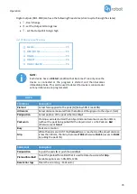
List of the important pins of the CNIN mating connector:
(viewed from the soldered surface)
Connector type: FCN-361J024-AU soldering type female (Fujitsu component)
Pin
Description
Pin Description
B1
Digital input 97
A1
Digital output 97
B5
Digital input 98
A5
Digital output 98
B2
Digital input 99
A2
Digital output 99
B6
Digital input 100
A6
Digital output 100
B3
Digital input 101
A3
Digital output 101
B7
Digital input 102
A7
Digital output 102
B4
Digital input 103
A4
Digital output 103
B8
Digital input 104
A8
Digital output 104
A10
M1 - Internal power 24V
B10 M1 - Internal power 24V
A11
P1 - Internal power 0V
B11 P1 - Internal power 0V
B9
Input common
A9
Output common
B12
PR (Relay power +)
A12 MR (Relay power -)
Please note which pin you used during the wiring, in a later step it is going to be needed for the mapping.
To have a common signal ground the following two pins needs to be wired together:
Pins from
Pins to
Description
Compute Box - GND
A11 (or B11)
Compute Box GND to P1 (Internal power 0V)
In case of a Relay type Mini I/O board the following CNIN pins needs to be wired together to power the
relays:
Pins from
Pins to
NACHI Signal
B12
A10 (or B10)
PR (Relay power +) to P1 (Internal power 24V)
A12
A11 (or B11)
MR (Relay power -) to M1 (Internal power 0V)
In addition, in order to set the Relay type Mini I/O board to NPN or PNP configuration the following CNIN
pins needs to be wired together:
•
For
NPN
configuration
Содержание Gecko Gripper
Страница 1: ...USER MANUAL FOR NACHI ROBOTS ORIGINAL INSTRUCTION EN v1 05...
Страница 12: ...Operationmode s 12 Mode I OnRobot EtherNet IP...
Страница 26: ...Installation 26...
Страница 47: ...Operation 47...
Страница 48: ...Operation 48 Mode II OnRobot WebLogic...
Страница 64: ...Installation 64...
Страница 106: ...Additional Software Options 106 HEX E H QC RG2 6 T Oassemblyid 150 T Odata size 40 bytes T Oparameters...
Страница 113: ...Additional Software Options 113 RG2 6 VG10 VGC10 T Oassemblyid 156 T Odata size 64 bytes T Oparameters...
Страница 115: ...Additional Software Options 115 O Tassemblyid 157 O Tdata size 64 bytes O Tparameters...
Страница 117: ...Additional Software Options 117 RG2 6 Gecko T Oassemblyid 158 T Odata size 64 bytes T Oparameters...
Страница 123: ...Additional Software Options 123...
Страница 135: ...Hardware Specification 135 RG2 FT GrippingSpeedGraph GripperWorkingRange The dimensionsare in millimeters...
Страница 139: ...Hardware Specification 139 RG2 GrippingSpeedGraph RG2 Work Range...
Страница 142: ...Hardware Specification 142 RG6 GrippingSpeedGraph RG6 Work Range...
Страница 162: ...Hardware Specification 162 9 2 Mechanical Drawings 9 2 1 Adapter plate s...
Страница 163: ...Hardware Specification 163 Adapter I...
Страница 164: ...Hardware Specification 164 Adapter J...
Страница 170: ...Hardware Specification 170 Gecko All dimensionsare in mm and inches...
Страница 171: ...Hardware Specification 171 RG2 FT All dimensionsare in mm and inches...
Страница 172: ...Hardware Specification 172 RG2 All dimensionsare in mm and inches...
Страница 173: ...Hardware Specification 173 RG6 All dimensionsare in mm and inches...
Страница 174: ...Hardware Specification 174 VG10 All dimensionsare in mm and inches...
Страница 175: ...Hardware Specification 175 All dimensionsare in mm and inches...
Страница 176: ...Hardware Specification 176 VGC10 All dimensionsare in mm and inches...
Страница 177: ...Hardware Specification 177 All dimensionsare in mm and inches...
Страница 178: ...Hardware Specification 178 Quick Changer Tool side All dimensionsare in mm and inches...
Страница 185: ...Certifications 185 12 Certifications...
Страница 186: ...Certifications 186...
Страница 187: ...Certifications 187...
Страница 188: ...Certifications 188...
Страница 189: ...Certifications 189...
Страница 190: ...Certifications 190...