OmniTek Ultra 4K Tool Box Скачать руководство пользователя страница 59

 --------------- Conversion Facilities: Additional SDI Output Features ---------------  

Ultra v2.0a User Guide 


G-3


G.2  Jitter Insertion 

A good way to determine the robustness of an SDI connection is 

by  subjecting  it  to  different  levels  of  jitter.  Where  the 

Ultra 

includes  the  PHY  and  PHY_ADV  options  plus  either  the 

GENERATE or the CONVERT option, it also offers facility to 

insert jitter into output video stream. The added jitter takes the 

form of a sine wave at your choice of frequency and your choice 

of level, up to the maximum that can physically be achieved. (This 

maximum depends on the frequency that you select.) 
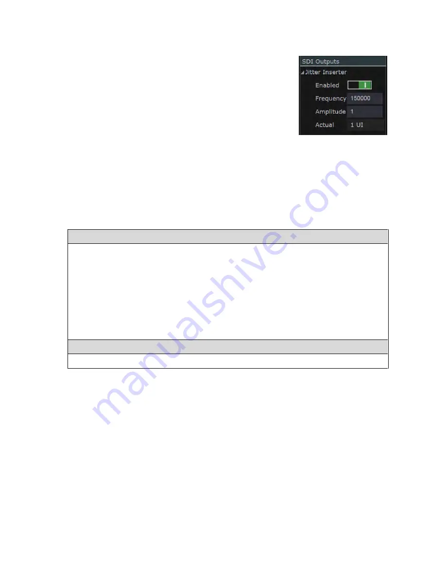
Jitter insertion is enabled and configured using the 

Jitter Inserter


settings  shown  in  the  right-hand  panel  when  the  block  of  SDI 

Outputs is selected on the Connections window. 

Note:

  Once  the  Jitter  Inserter  has  been  enabled  (

1

),  jitter  will  be 

inserted in all SDI output until the Jitter Inserter is disabled again (

0

). 

You should also note that where the output is being analysed by Jitter Meters such as the ones 

offered by the 

Ultra

, the sinusoidal nature of the applied jitter means that the jitter measured after 

passing through a high-pass filter of the same frequency will be 3dB down from the specified 

amplitude. 

To add insert jitter to SDI output:


On the Connections window: 

1.


Click on the header line of the block of 

SDI Outputs

2.


Under the heading 

Jitter Inserter

 in the right-hand panel, set the 

Enabled

 option to On (

1

3.


Set the 

Frequency

 to the frequency of the required jitter (in units of kHz). 

4.


Set the 

Amplitude

 to the desired number of UI.  

The nearest number of UI that can be achieved will then be displayed as the 

Actual

 value.  

Note: 

Amplitude and Frequency settings that are greater than the maximum achievable are 

automatically truncated. 

To stop adding jitter to the output:  


Set the 

Enabled

 option to Off (

0

). 


Figure G-3:


Jitter Insertion section of the 

right-hand panel. 

Содержание Ultra 4K Tool Box

Страница 1: ...Ultra 4K Tool Box User Guide Version 2 0a August 2015...

Страница 2: ...d revisions hereto or new additions may be issued to incorporate such changes Warranty Omnitek systems are warranted for one year from date of purchase This includes all feature upgrades and bug fixes...

Страница 3: ...stem Facilities A 19 A 5 3 Updating to the Latest Version A 20 A 5 4 Installing Additional Facilities A 20 B System Configuration Control B 1 B 1 Inputs Outputs Internal Connections the Connections wi...

Страница 4: ...ng between Full Screen and Multiple Tile displays H 3 H 2 3 Configuring a View H 5 H 3 Focus of Analysis H 5 H 4 Saving and Recalling Specific Tile Selections H 6 I Pixel Data I 1 I 1 The Focus of the...

Страница 5: ...2 Set Up S 3 S 2 Eye Waveform S 4 S 2 1 Selecting the Eye Waveform display S 5 S 2 2 Configuring the Eye Waveform display S 5 S 2 3 Obtaining Signal Parameters from the Eye Waveform S 6 S 2 4 Transmi...

Страница 6: ...V 6 Playing Out a Series of Test Patterns V 8 W Creating Test Patterns W 1 W 1 Line Colour Bar Patterns W 1 W 1 1 Adding a New Line Pattern W 1 W 1 2 Configuring the Line Pattern W 2 W 1 3 Modifying...

Страница 7: ...ntrolled It also gives general maintenance advice and describes the steps used to upgrade to the latest version of the Ultra software and to add software options Note Throughout this guide steps are d...

Страница 8: ...General Ultra v2 0a User Guide...

Страница 9: ...fied and take the following safety precautions Where the Ultra is being used alongside other equipment you must also ensure that you act in accordance with the advice given in the documentation suppli...

Страница 10: ...n Support for 12G SDI is available as an optional extra Note A full list of the video standards supported by Ultra systems can be downloaded from the Manuals etc page of the Omnitek website Configurat...

Страница 11: ...ition of PHY_ADV option extends the range of signal standards supported to include 12G and adds Jitter Spectrum Jitter Histogram and Jitter Insertion for test purposes to the facilities offered Test S...

Страница 12: ...UX 3 4 SDI Outputs SD HD 3G 6G 12G DisplayPort 1 2 Output DisplayPort 1 2 Input Not implemented in this version SDI Eye Input SD HD 3G 6G 12G SDI 1 3 Bidirectional SD HD 3G SFP Cage Composite USB2 por...

Страница 13: ...use good quality 75ohm coax cable The SDI inputs and outputs on the Omnitek Ultra system have been tested characterized and calibrated using Belden 1694A cable with Neutrik BNC terminations A 1 4 Inst...

Страница 14: ...Jitter insertion for test purposes output voltage slew rate control Note The range of options available on any Ultra system is defined by the licences that are currently installed on that system Infor...

Страница 15: ...g carton and all packing materials in case you subsequently need to ship the Ultra anywhere A 2 2 Typical Set Up The typical set up used to work with 4K input or output comprises Ultra and PSU PC Hand...

Страница 16: ...s Connections window These settings are explained in Section B 1 8 However it is possible to have some of these settings made for you as part of the process of powering up the Ultra To take advantage...

Страница 17: ...reference clock The Ultra can be linked both to the source of the reference signal and to other instruments using the same reference signal through the Composite connector on the back panel The refere...

Страница 18: ...ront panel The power button will become lit and the Ultra will then load the Ultra application Note This will take a few seconds 3 If a dialog appears on your HDMI monitor offering the option of keepi...

Страница 19: ...bers only without any spaces hyphens or other characters Using the Machine Host Name Important Not all networks will support this action Where not supported you will need to use the Ultra s IP address...

Страница 20: ...into pages covering different aspects of the Ultra s system configuration So inspecting or changing any detail of the system configuration involves first calling up the Configuration window then selec...

Страница 21: ...set is given in Section A 4 3 Tabs at the bottom of the display where included select different pages of information The current page is highlighted in blue A 4 3 User Interface Controls Note Where th...

Страница 22: ...y that is open to view below The steps generally used to navigate these structures are given below Note Where special steps are needed to navigate a hierarchical display these steps are explained alon...

Страница 23: ...being edited To select Press Yes option Alt Y key No option Alt N key or ESC OK option Alt O key Cancel option Alt O key or ESC Next Control option Tab key To close the Dialogue Box ESC Navigation on...

Страница 24: ...lections of Test Patterns is saved and recalled using Export Import options Presets are identified by number 1 2 3 etc and the role of the Presets toolbar is to enable you to select the Preset you req...

Страница 25: ...l save the specified item to your web browser s Downloads directory or another directory as described above A symbol is used for the corresponding Upload option where appropriate A 5 System Informatio...

Страница 26: ...n the web browser using the URL IP address where IP address is a placeholder for the dotted quad given on the System page If no IP address is shown the Ultra is not connected to a suitable network Net...

Страница 27: ...s described in Section A 5 4 Where a facility is listed as No Hardware however extra hardware is needed in order to support this option Where this is the case you may need to return the Ultra either t...

Страница 28: ...files on a PC on the same network as the Ultra 5 Follow the appropriate set of steps given in the Upgrade Instructions Note There is no need to formally unmount the USB stick at the end of the operati...

Страница 29: ...window depends on the options installed on the Ultra you are using In particular The link between the Eye input and the Physical Layer Analyser block will only be offered where the PHY option is inst...

Страница 30: ...nterface can only be output on the HDMI output port There is no external output from the Physical Layer Analyser block SDI video is delivered over 1 2 or 4 cables depending on the video format so the...

Страница 31: ...marker will be on the right hand side of the block 2 Drag to the corresponding marker representing the input to the block to which you want to make the connection This marker will typically be on the...

Страница 32: ...d output ports can continue to be used to output the generated signal to external equipment as these ports are not required for feeding the output into the Ultra s Analyser Converter To help you selec...

Страница 33: ...ses the opposite convention to the way the Ultra is configured the image will be displayed with the right and left panels swapped This is readily rectified through the Swap monitor tiles option offere...

Страница 34: ...right is displayed 2 Starting with the Interface entry click on the down arrow to the right of the current selection and pick the required option from the drop down list that is displayed 3 Use the sa...

Страница 35: ...how the incoming data is interpolated is set by a filter associated with the Analyser Converter The choice of filter is important for example where the resolution of the active picture is changed beca...

Страница 36: ...ut and setting up the Connections window to link the Local User Interface block to the HDMI Output All that achieves is a copy of the User Interface exactly as displayed via the Web i e with no image...

Страница 37: ...l the Configuration settings to their original values and one that returns all aspects of the Ultra to the state in which it was initially shipped This Factory Reset should be used with extreme care T...

Страница 38: ...se Floor in Section S Error Checking Threshold values for all the different parameters monitored by the Ultra together with settings defining the required response if any to the signal going over this...

Страница 39: ...4 9 16 9 or defining your own Variable cage sizes The Default fixed sizes settings selects the set of standards to follow the Safe title and Safe action entries either select one of the standard scree...

Страница 40: ...es a value is set which gives the number of such errors that can happen per frame before an error should be reported Active Picture EDH CRC errors and Full Raster EDH CRC errors are counted separately...

Страница 41: ...arameters on the System page of the Configuration window Connection Presets record the inputs outputs video standards etc selected on the Connections window see Section B 2 and Section D Up to 9 Prese...

Страница 42: ...table description as the Name for the Preset then select OK The purpose of this name is to aid identification It is shown briefly at the top of the display when the mouse pointer hovers over the Prese...

Страница 43: ...ured in the same way so a particular set of User Presets will modify the configuration in the same way on any system It is therefore possible to set up one system to match another system by saving the...

Страница 44: ...section import a set of Presets that have been previously been exported either from this Ultra or from another Ultra into the Ultra on which this procedure is carried out There are no restrictions on...

Страница 45: ...unique to the manufacturer of the system it is being used with but that manufacturer can choose to use the same MIB file across a number of similar systems and across different versions of a system T...

Страница 46: ...ort picked out in the following figure To create the required network 1 Use a suitable cable to physically connect each Ultra to the same network router 2 Link the control device into the same network...

Страница 47: ...e 2 Download the MIB file by selecting the symbol next to SNMP MIB in the Files area to the right of the System page The file is downloaded to the Downloads directory associated with the web browser y...

Страница 48: ...es the browser to read the values from the selected Ultra The raw form of this data is not easy to sort through but iReasoning includes the option to show certain areas of the data in a Table View in...

Страница 49: ...pment test By automating the various selections involved the engineer becomes free to concentrate on spotting where problems arise While the OIDs used by SNMP appear complex the task of programming th...

Страница 50: ...General Automated Control Ultra v2 0a User Guide C 6...

Страница 51: ...ormat of the input signal In the current version these facilities include Switching the delivery format of the signal e g between SDI and HDMI Switching the video standard It also describes the InterL...

Страница 52: ...Conversion Facilities Ultra v2 0a User Guide...

Страница 53: ...tween the two sets of delivery formats and video standards is an intrinsic consequence of feeding in input using one delivery format video standard and specifying a different delivery format and or vi...

Страница 54: ...Connections window i Between the input port you are going to use and the input to the Analyser Converter block in the central column of the screen display and ii Between the output from the Analyser...

Страница 55: ...tion from the drop down list that is displayed 3 Use the same procedure to set the Raster setting then the Refresh then the Sampling 4 When all entries have been set to define the required video stand...

Страница 56: ...Filter setting associated with the Analyser Converter The steps to use are outlined below For further information see Section B 1 7 To set the interpolation algorithm that is applied Click on Analyse...

Страница 57: ...l times of the output from SDI 4 These adjustments are all made through the right hand panel of the Connections window These options are included on the Ultra in order to allow you to produce signals...

Страница 58: ...be moved either by dragging the white bar or by typing the required value in the adjacent box The range of values supported is between 128 and 127 corresponding to advancing delaying the selected sig...

Страница 59: ...ted in all SDI output until the Jitter Inserter is disabled again 0 You should also note that where the output is being analysed by Jitter Meters such as the ones offered by the Ultra the sinusoidal n...

Страница 60: ...anel of the Connections window when the block of SDI Outputs is selected The mV setting selects a signal amplitude between 450 and 900mV the Slew Rate has two possible settings Fast which gives normal...

Страница 61: ...hat includes the ANALYSE option offers a wide choice of signal analysis displays These are described over the next few sections of this User Guide Note An Ultra that doesn t include the ANALYSE option...

Страница 62: ...Signal Analysis Ultra v2 0a User Guide...

Страница 63: ...rence Timing measurements This section looks at the overall features of the Viewer window The displays associated with the different analysis tools that may be applied are described in a separate sect...

Страница 64: ...n of the Status display There is generally no point in displaying a second version of a View that is already displayed as the copies will be configured in the same way and always show the same informa...

Страница 65: ...to having a second copy of a View because exactly the same information is shown in each copy it makes a great deal of sense to have for example two or more tiles devoted to displaying different pages...

Страница 66: ...en display For the Picture View the pattern is extended to include the full screen display without a Title Bar and a special procedure is needed to return from this state to the Multiple Tile version...

Страница 67: ...nd the Data Waveform described in Section L just show results from a section of a particular line while the Zoom View described in Section K just shows the pixels around a particular point in the curr...

Страница 68: ...direction and then back again can leave you in a very different position to where you started if you fail to notice a change in the selected Input Further details are given in the appropriate sections...

Страница 69: ...aved iii Ancillary Data Viewer Section I 4 Displays a decode of any ANC packets detected at the current cursor position In each case the focus for the display is linked to the current X Y positions in...

Страница 70: ...rsors are shown within Active Picture and SMPTE Sample cursor roses shown in the right hand panel of the Viewer window Additionally their respective cursors can be moved right left up down by clicking...

Страница 71: ...the required Input from the drop down list associated with the Input entry shown at the bottom of the SMPTE Sample cursor rose Note Inputs are identified by n m numbers where n is the number of the ca...

Страница 72: ...own on the other line Whether the U V value shown should be interpreted as U or V is shown by the coloured bar at the bottom of the column which is blue for U values and red for V values In other part...

Страница 73: ...uring scheme used in the appropriate SMPTE standard An alternative Cable centric view is available in which the data is arranged in line with how it is delivered by individual cables again coloured in...

Страница 74: ...s or Split into an 8 bit value and a two bit both expressed in hex The last of these options is useful in making standard groupings such as those associated with SAV and EAV easier to pick out The dif...

Страница 75: ...age Use the techniques described in Section I 1 to move to the required position To set the data format Click the Format button on the Button Bar until the required data format is selected Clicking th...

Страница 76: ...ut from which data is shown Click the required Input on the Button Bar The selected Input will become highlighted To display ANC Packets from the Y C streams 1 Click on the Ancillary Data Viewer to ma...

Страница 77: ...in the Viewer however web based versions of the User Interface such as that shown where a PC or a handheld is used as the Control device are not able to support full resolution images At the time of...

Страница 78: ...to the Local User Interface and to direct the Local User Interface to the HDMI output port Figure J 3 Connections needed on the Connections window to display Full Resolution Images The steps needed to...

Страница 79: ...ll set the aspect ratio based on the Active Format Description embedded in the selected input Cage The Cage option controls the display of Safe Action and Safe Title cages see Section J 4 Capture The...

Страница 80: ...n to Off 0 To position the crosshair cursor Either Click the required position on the Picture View Or Drag the crosshair cursor to the required position Or Click on the arrow symbols of either the Act...

Страница 81: ...ions allow you to specify the dimensions you require Opting for a Variable safe title cage also allows you to choose where this cage is positioned Both types of cage can be marked out using either a s...

Страница 82: ...splayed move the Dashed setting to On 1 or Off 0 as required When Dashed is set to Off 0 the cage will be displayed as a solid line To specify a Variable Cage 1 Display the Video page of the Configura...

Страница 83: ...y you might opt to set Dashed to On 1 for Safe title 1 and Safe title 2 but Off 0 for Safe action 1 and Safe action 2 to allow you to readily distinguish between Safe title and Safe action cages To di...

Страница 84: ...ver the zoomed image or if the mouse pointer isn t on the zoomed image about the pixel at the current cursor position The data shown comprises the Y U and V values of the selected pixel in the current...

Страница 85: ...SMPTE range colour values and gamma correction The user may also specify the Reference White Level to be used in converting the image between XYZ and other colour spaces Note The number of frames that...

Страница 86: ...r Interface block to the HDMI Output The Ultra s User Interface should now be shown on the HDMI monitor 3 Show the Viewer window on the HDMI monitor 4 Click on the down arrow in the Title Bar of one o...

Страница 87: ...as a Test Signal on the same Ultra if this includes the Generator or saved to disk by using the Export option described in Section W 4 To save captured images 1 Select the required set of frames in th...

Страница 88: ...played in the bottom right hand corner of the Generator window The default allocation corresponds to 25 of the Ultra s available memory with the rest of this memory being allocated to holding Generato...

Страница 89: ...ple Single and Double versions of the Data Waveform display In common with the various Pixel Data displays described in Section J the focus for the display is linked to the current X Y positions indic...

Страница 90: ...that is displayed To set the scope of the display to 15 or 31 pixels Click the appropriate button on the Button Bar Single for 15 pixels Double for 31 pixels To set the format used for YUV values Clic...

Страница 91: ...that can be shown on the Viewer window It comprises a set of bar graphs each showing the range of values for one of the different colour components in the video currently being analysed The display i...

Страница 92: ...e section of Video page of Configuration window The display is divided into separate sections covering YCbCr and RGB colour spaces The YCbCr section allows you to set separate maximum and minimum valu...

Страница 93: ...dow The pages of the display are each associated with a particular button on the Button Bar In some cases just one page is called up by pressing the associated button but pressing the Video button and...

Страница 94: ...sted as required on the Video page of the Configuration window Further details are given where this page of the Configuration window is described Section B 2 1 O 1 3 Resetting Error Counts The second...

Страница 95: ...ideo data stream For instance the ANC entry counts invalid ANC checksums The Line entry counts TRS packets where the line number specified does not agree with the line number calculated internally Not...

Страница 96: ...Signal Analysis Status Ultra v2 0a User Guide O 4...

Страница 97: ...signal amplitude rise fall times jitter and timing Some of these facilities are provided as standard on the 4K Tool Box and become available on other Ultra systems by adding the PHY option Extending...

Страница 98: ...Physical Layer Analysis Ultra v2 0a User Guide...

Страница 99: ...r an initial set up period in which the sampling builds up sufficient data it becomes possible to determine parameters such as the signal amplitude the unit interval the rise time and the fall time of...

Страница 100: ...n that switching the output from a video standard that requires one fundamental clock to a video standard that requires the other clock doesn t just interrupt the output but also causes glitches in th...

Страница 101: ...d in working with these displays as are used with other Views see Section H Further information is given on the Physical page of the Status View see Section O It is expected that the main displays to...

Страница 102: ...lay A number of signal quality assessments can be determined from an Eye Waveform The main ones are the signal amplitude eye height determined from analysis of the section of the Eye Waveform marked b...

Страница 103: ...when the Eye Waveform display is selected The Colour scheme used set in right hand panel The Jitter meter shown alongside the Eye Waveform set using Button Bar The method used to determine Eye Amplitu...

Страница 104: ...Method set on that page The rise and fall times are determined as shown in Figure S 5 Accuracy of Eye Rise Fall Time Measurements The accuracy to which the Ultra measures rise and fall times differs a...

Страница 105: ...tion of the clock edges in the carrier signal that is being analysed Alongside each solid marker is an open marker that shows the current instantaneous jitter value The upper bound of the pass band in...

Страница 106: ...ection B 2 1 and is set individually for each video standard class SD HD 3G etc and each High Pass Filter 10Hz 100Hz 1kHz 10kHz 100kHz To set the Meter Scale and the Colour Transition Points 1 Show th...

Страница 107: ...ither parameter more clearly You also have the option of freezing the display to allow further inspection including looking at parts of the frequency spectrum that are not currently shown The peaks ar...

Страница 108: ...ncies is between zero and the Range value set in the right hand panel displayed when the Jitter Spectrum is selected This range is expressed in terms of the unit interval UI of the data signal Any val...

Страница 109: ...ollected data from the mean is shown towards the top of the display Figure S 12 Jitter Histogram display Where the jitter is truly random the distribution will take the form of a simple Gaussian curve...

Страница 110: ...5 Jitter Waveform Requires PHY_ADV The Jitter Waveform display comprises a trace of the jitter detected in the data carrier signal shown as a graph of amplitude against time in a choice of colours Th...

Страница 111: ...Hz as the lower bound of the pass band selecting 10 s as the time base corresponds to selecting 100kHz as the lower bound of the pass band To set the High Pass Filter that is applied Select from the B...

Страница 112: ...Physical Layer Eye Jitter Ultra v2 0a User Guide S 14...

Страница 113: ...delayed relative to the Reference signal named at the top of the display For example the meters shown in the above example show the timing of a set of four SDI Inputs relative to the first of those In...

Страница 114: ...e Composite port on the Ultra If however you are intending the compare the Ultra s measurements against the measurements produced by another system there may be other settings to make in order to ensu...

Страница 115: ...igure T 3 Timing section of the Video Configuration page T 3 Comparing the Timing of Constituent Inputs Where video is delivered over two or more separate Inputs the relative timing of these Inputs ca...

Страница 116: ...ysis Figure T 5 Timing display set up to compare against an External reference To compare timing against an External reference 1 Feed a suitable reference signal into the Composite port on the Ultra s...

Страница 117: ...ions of these The chapters in this section of the Ultra User Guide describe the steps used to set up the required Test Patterns and play them out either singly or in sequence They also describe the va...

Страница 118: ...Generator Ultra v2 0a User Guide...

Страница 119: ...test patterns Adjust the properties of images etc used as test patterns The various options it offers are described across Sections V W and X of this User Guide Figure V 1 Example Generator window dis...

Страница 120: ...patterns can also be modified before play out for example by setting segments of the image to pan at different speeds V 1 1 Selecting the Generator Window To display the Generator window Select the Ge...

Страница 121: ...st patterns The steps required to use sequences of such images as test patterns are slightly different and are described in Section V 3 V 2 1 Importing Still Images Use the following steps to create a...

Страница 122: ...described in Section X 6 If necessary adjust the timing relative to the chosen Genlock as described in Section B 1 6 7 Where SDI outputs are used there are further adjustments that can be made see Se...

Страница 123: ...lick on the Create Sequence option in the Button Bar at the bottom of the screen 2 Set the Sequence type to Sys OmnitekTSA or Sys OmnitekTSA 4kMarkers as required 3 Set the required duration in second...

Страница 124: ...e number within the file name does not change The number must also increment contiguously Examples of incorrect filenames Test_7 Test_8 Test_9 Test_10 Test_11 Test_12 The digits are not of fixed lengt...

Страница 125: ...ative route is offered by right clicking See below for details To delete a test pattern from the Generator window Note The following steps just delete the thumbnail associated with the test pattern th...

Страница 126: ...which each pattern is played are given below To play out a sequence of patterns 1 Arrange that the Generator window just contains the images colour bars zone plates etc you want to play out and that t...

Страница 127: ...pattern and add a thumbnail for the pattern in the main part of the screen The line pattern can then be configured as described below combined with a zone plate as described in Section W 3 and played...

Страница 128: ...source image is currently selected can be seen both by spotting which thumbnail is highlighted and from the Title entry in the right hand panel 2 For each segment that you want to use display the dro...

Страница 129: ...is therefore principally a matter of setting the appropriate multipliers It is however notoriously difficult to determine what multipliers to use to achieve a specific result so the Ultra offers some...

Страница 130: ...ndow If necessary click on the zone plate s thumbnail to select it Which pattern is currently selected can be seen both by spotting which thumbnail is highlighted and from the File entry in the right...

Страница 131: ...re therefore the steps to use whenever you want to change how the zone plate is displayed Note The pattern you create is automatically saved on the Ultra s Flash disk but will be removed if you either...

Страница 132: ...an only be used either to restore a test pattern that has been deleted or to duplicate a pattern set up on one Ultra on another Ultra Details are given below both of the steps used to export test patt...

Страница 133: ...enerally slower alternative is to use Windows Explorer or equivalent to navigate to the Downloads directory W 4 2 Importing Saved Test Patterns Test Pattern Sets The steps used to add test patterns th...

Страница 134: ...Generator Creating Test Patterns W 8 Ultra v2 0a User Guide...

Страница 135: ...a content can be adjusted e g by specifying a different gamma Sections of the pattern can be made to pan as the Test pattern is played out In some cases the required adjustment is made by changing how...

Страница 136: ...adjusted to fit the selected output standard Fit horizontal vertical i e both the width and the height are to be adjusted to fit the selected output standard None i e no re sizing If it is important t...

Страница 137: ...If the image you are using as the source for a test pattern was recorded using some over value of gamma you can switch the interpretation as described below To change the Gamma that is applied 1 Clic...

Страница 138: ...ts as you want to pan Switch that segment to On 1 Set Start to the start line of the segment Set Height to the number of lines in the segment Set the required Speed between 1 slowest and 63 fastest No...

Страница 139: ...Ultra v2 0a User Guide...

Страница 140: ...Intec Unit 3 Level 1 Wade Road Basingstoke Hants RG24 8NE UK Tel 44 0 1256 345900 Fax 44 0 1256 345901 Email support omnitek tv Web www omnitek tv...

Отзывы: