710.1760.00.04-05
22/05/2014
20
7)
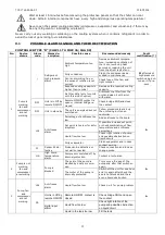
Ensure that the motor protection switches (“MTC” and “MTP”) are in position “0”.
8)
Move the motor protection switches of the chiller to position “1”.
9)
Make sure that the oil is able to circulate adequately. It the circuit might be interrupted by something such as
a valve, electrical valve, a filter or anything else, a by-pass circuit (automatic overflow valve) must be in-
stalled in order to prevent damage to the pump.
10)
Lock the switch cabinet with the key.
11)
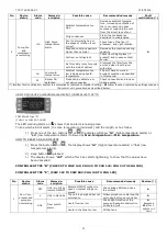
Move the main switch of the chiller to position “1” (the temperature of the cooling medium is displayed).
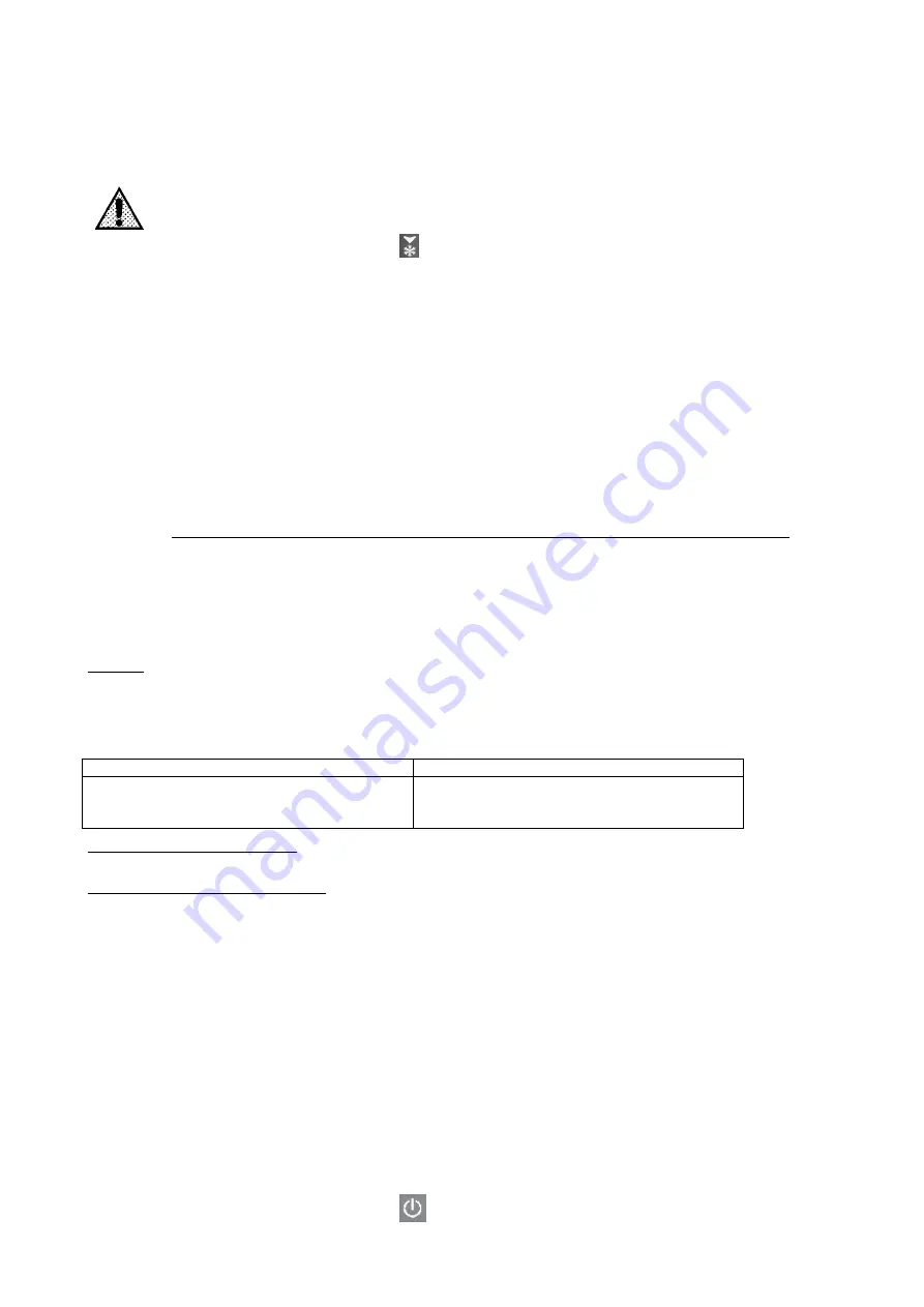
Never touch any part of the refrigeration circuit when the chiller is running!
12)
Start up the compressor by pressing the
button for 3 seconds.
13)
Wait until the chiller has attained the operating conditions. This is indicated when the display shows the preset
working range.
14)
Because the pump starts up immediately, make sure that the direction of rotation for the pump matches the
direction of the arrow on the casing. If it is rotating in the opposite direction, turn off the main switch of the
chiller immediately and arrange for the polarity of the chiller to be reversed.
15)
After a few minutes carefully open the filler screw again in order to remove any residual air. Tighten the screw
again afterwards.
16)
Check whether the pressure shown is within the limits specified for the pump. If not, take appropriate action
to ensure that pump is able to run within the specified limits.
17)
Wait for the compressor to switch on. The compressor symbol will appear on the display (see Section 6.4).
18)
Check the inside of the chiller and the piping system for leakage or loose connections.
19)
Fit the front panel and the two side panels back onto the casing.
20)
The chiller is normally factory-set to the temperature required by the customer.
21)
When the chiller is within the operating conditions set by the manufacturer, check whether the current uptake
of the chiller matches the data indicated on the identification plate and those contained in the table in the
supplement.
6.3
CHECK LIST FOR COMMISSIONING GLYCOL RECIRCULATING CHILLERS
After turning off the main switch for more than 1 hour or after extraordinary maintenance work, each
chiller start should be regarded as an initial start-up.
The initial start-up calls for a number additional checks to ensure safe and reliable performance of the
system.
REQUIREMENTS FOR THE WATER-GLYCOL MIXTURE
Quality:
A water-glycol mixture should be used for filling the chiller (glycol = ethylene glycol). Corrosion-inhibiting
additives may also be included provided they are explicitly authorized for this purpose by the manufac-
turer concerned. The glycol content must be at least 20% and should not exceed 25%.
Cold water discharge temperature
Ethylene glycol in %
± 0°C
- 5°C
- 10°C
20
20
25
General operating conditions:
The glycol recirculating chiller is designed for cooling medium temperatures of -10°C to ±0°C.
Conditions during commissioning:
Should liquid temperatures different to those described in the general operating conditions occur during
the initial start-up, be sure to contact the manufacturer.
CHECKLIST FOR CHG 08 TO CHG 365
Controller Type “D”, see 6.4 (CHG 08)
1)
Remove the upper lid panel and the two side panels.
2)
Open the tank cap and fill the tank (using a T-fitting if necessary) while watching the level indicator (refer to
Fig. 1, Point 5.2.1).
3)
Open the filler screw on the pump head.
4)
Tighten the screw again when only cooling medium flows out.
5)
Open the shut-off valve.
6)
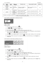
Move the main switch of the chiller to position “1” (the display will show “OFF”, and the pump will start to
run).
7)
Top up the tank again if too much cooling medium has flowed out of the shut-off valve. Fasten the tank cap
again afterwards.
8)
After a few minutes carefully open the filler screw again in order to remove any residual air. Tighten the screw
again afterwards.
9)
Replace the upper lid panel and the two side panels.
10)
Start up the compressor by pressing the
button.
Содержание CHG 08
Страница 39: ...710 1760 00 04 05 22 05 2014 39 1 1 1 CHW CHO CHG chiller CHW CHO CHG 1 2 CHW CHO CHG CHW CHO CHG CHW CHO CHG 2...
Страница 40: ...710 1760 00 04 05 22 05 2014 40 CHW 20 25 CHO 10 cST CHG 20 25 5 EN 60204 EN 378 2...
Страница 41: ...710 1760 00 04 05 22 05 2014 41 HFC CE 842 2006 3 3 1 3 2 C CND EVA HP LP...
Страница 42: ...710 1760 00 04 05 22 05 2014 42 MHP MLP PV R V a 2 5 b VE 2 5 MOP IAF 3 3 MF P...
Страница 43: ...710 1760 00 04 05 22 05 2014 43 BP BPM CAA EV 1 1 VNR FL LVE RA TD VNR EV 1 2 3...
Страница 44: ...710 1760 00 04 05 22 05 2014 44 1 2 3 4 5 6 7 3 4 ALR...
Страница 48: ...710 1760 00 04 05 22 05 2014 48 CHW 97 CHW 3652 4 2 4 3 5 50 C 12 6 5 2 5 5 1 2 C 40 C 2 C 40 C...
Страница 50: ...710 1760 00 04 05 22 05 2014 50 25 1 60 CHO A B C D E Abb 1 TN C 230 1 1 N PE AC 400 3 3 PEN AC PEN...
Страница 65: ...710 1760 00 04 05 22 05 2014 65 CHW 682 CHW 3652 CHG 225 CHG 365 6 4 1 2 0 0 5 2 1...
Страница 67: ...710 1760 00 04 05 22 05 2014 67 5 6 8 9 10 3 20 15...
Страница 68: ...710 1760 00 04 05 22 05 2014 68 9 1 A CHW 11 CHW 36 CHG 08 1 OFF A OFF LA2 P1 SL HA 2 A 3 LA2 2 A CA 4 HA A...


