710.1760.00.04-05
22/05/2014
13
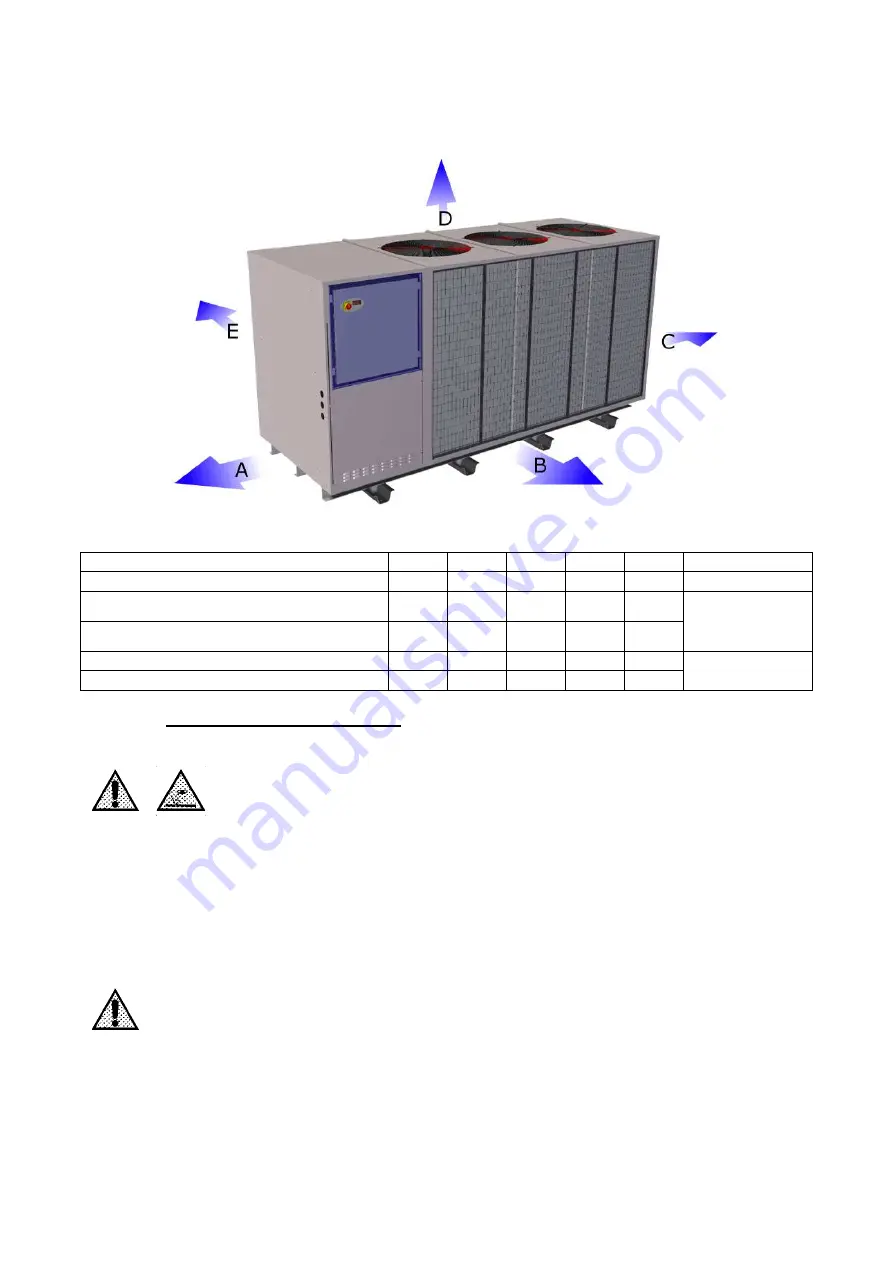
Position the chiller so that the instrument displays can be read easily and the controls can be easily ac-
cessed.
Allow sufficient space for the possible installation of further components.
There must be sufficient free space above the chiller to ensure that air can flow freely to cool the conden-
ser.
(Sample illustration. See the corresponding letters for the other versions. B is always the front side)
Models
A (m)
B (m)
C (m)
D (m)
E (m)
LOCATION
CHW 09 to 36, CHG 08
1
1
1
1
1
Indoors
CHW 29 to 67, CHO 29 to 67,
CHG 24 to 45
1
1
1
1,5
1
Sheltered outdoor
location
CHW 97 to 149, CHO 97 to 149,
CHG 75 to 100
1
1
1
2
1
CHW 162 to 1202, CHG 140 to 365
1
1
1
3
1
Outdoors (shelter
recommended)
CHW 1452 to 3652
1
2
1
4
2
5.2
ASSEMBLY (CONNECTIONS)
CONNECTION TO THE REFRIGERANT CIRCUIT (CONSUMER CIRCUIT)
All work may only be carried out by specialist personnel!
Procedure:
-
In closed systems, make sure that the maximum obtainable cooling medium pressure in
the supply line does not cause a higher pressure level than the maximum permitted for
the chiller.
-
Check the cleanliness of the supply line and the piping system to be connected.
-
Connect the chiller with the consumer circuit; the identification of the joints (cooling me-
dium inlet/outlet) is indicated on the chiller by means of the symbols described in the in-
troduction to the manual.
-
Make all the connections, without rotating the sleeves located on the hose.
The cooling medium circuits of the Series CHW and CHG with tank are open to the atmosphere
as standard!
Use piping, connections and fastening components with a cross-section to match the capacity of the
chiller and the possible volume flow. This should not be smaller than the diameter of the chiller connec-
tions.
In the case of rigid connections, check during the initial start-up of the chiller that it is not subject to any
vibrations that might endanger the integrity of the components.
We also recommend that you should plan to install the following system components:
Содержание CHG 08
Страница 39: ...710 1760 00 04 05 22 05 2014 39 1 1 1 CHW CHO CHG chiller CHW CHO CHG 1 2 CHW CHO CHG CHW CHO CHG CHW CHO CHG 2...
Страница 40: ...710 1760 00 04 05 22 05 2014 40 CHW 20 25 CHO 10 cST CHG 20 25 5 EN 60204 EN 378 2...
Страница 41: ...710 1760 00 04 05 22 05 2014 41 HFC CE 842 2006 3 3 1 3 2 C CND EVA HP LP...
Страница 42: ...710 1760 00 04 05 22 05 2014 42 MHP MLP PV R V a 2 5 b VE 2 5 MOP IAF 3 3 MF P...
Страница 43: ...710 1760 00 04 05 22 05 2014 43 BP BPM CAA EV 1 1 VNR FL LVE RA TD VNR EV 1 2 3...
Страница 44: ...710 1760 00 04 05 22 05 2014 44 1 2 3 4 5 6 7 3 4 ALR...
Страница 48: ...710 1760 00 04 05 22 05 2014 48 CHW 97 CHW 3652 4 2 4 3 5 50 C 12 6 5 2 5 5 1 2 C 40 C 2 C 40 C...
Страница 50: ...710 1760 00 04 05 22 05 2014 50 25 1 60 CHO A B C D E Abb 1 TN C 230 1 1 N PE AC 400 3 3 PEN AC PEN...
Страница 65: ...710 1760 00 04 05 22 05 2014 65 CHW 682 CHW 3652 CHG 225 CHG 365 6 4 1 2 0 0 5 2 1...
Страница 67: ...710 1760 00 04 05 22 05 2014 67 5 6 8 9 10 3 20 15...
Страница 68: ...710 1760 00 04 05 22 05 2014 68 9 1 A CHW 11 CHW 36 CHG 08 1 OFF A OFF LA2 P1 SL HA 2 A 3 LA2 2 A CA 4 HA A...


