background image

43

69

Deutsch

Español

Slovensky

VORBEITUNG DER MASCHINE FÜR DIE

ZERSTÄUBUNG VON PULVERPRODUKTEN

PREPARACION DE LA MAQUINA PARA LA

DISTRIBUCION DE LOS PRODUCTOS EN POLVO

PRÍPRAVA STROJA NA ROZPRAŠOVANIE 

PRÁŠKOVÝCH PRÍPRAVKOV

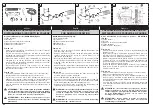
OPTIONALER Bausatz für Pulververteilung (Abb.65):
1) Schlauch einführen
2) Regler
3) Kupferdraht und kette
4) Mischrohr
5) Stelle die Buchse

ABB. 66 - 67

Schraube (6) abschrauben, Distanzhalter (7) entfernen und 


-

Sprührohr (10) aus der Bogenstutze (8) herauszziehen.
Buchse (9) aus dem Sprührohr (10) herausnehmen und an deren 


-

Stelle die Buchse (5) mit Leitblech einsetzen (Buchse 5 wie in 
der Zeichnung gezeigt einsetzen).
Sprührohr (10), Distanzhalter (7), die ganze Kette (3) und 


-

Schraube (6) wiedereinbauen. Sicherstellen, daß das Förderrohr 
(10) frei drehen kann, um die Dosierung der austretenden 
Pulvermittel zu gewährleisten. Sollte das Rohr festsitzen, 
Schraube (6) lockern.
Stopfen (13) vom Sprührohr (10) entfernen und den Kupferdraht 


-

(14) in die Bohrung einführen. Die Kette (15) freilassen, damit sie 
Bodenberührung hat.

ABB. 68 - 69

Den Filter (16), das Rohr (17) und den Anschlußstutzen (18) vom 


-

Tank entfernen.
Mischrohr (4) und Regler (2) einsetzen.


-

Das durchsichtige Rohr (20-21) und die Reduktion (22) vom 


-

Anschlußteil (19) entfernen: Schlauch (1) einführen; das andere 
Ende muß in das Rohr (10) eingeführt werden, nachdem der 
Veschlußdeckel (13) abgenommen worden ist.
Die Pulvermittel werden durch Drehen des Rohres (10) dosiert; 


-

dabei können die Fôrdermengen anhand der Skala (12) beim 
Stopfen (13) eingestellt werden.

ACHTUNG! – Es ist extrem wichtig, auf jeden Fall immer 
die Kupferkette (3, Abb. 65) zu benutzen. Durch 
Nichtbenutzung kann die Entzündung der entzündlichsten 
Pulver (Schwefel, usw.) aufgrund elektrostatischer 
Entladungen verursacht werden.

ACHTUNG! – Die Pumpe Booster nicht für die Verteilung 
pulverförmiger Produkte benutzen. Sie könnte dadurch 
ernsthaft beschädigt werden. 

Kit para aplicación de polvos, OPCIONAL (Fig. 65):
1) Tubo flexible
2) Dosador
3) Cable de cobre con cadenilla
4) Dispositivo agitador de los polvos
5) Buje reductor

FIG. 66 - 67

Destornillar el tornillo (6), quitar el separador (7) y el tubo difusor 


-

(10) de la curva de empalme (8).
Quitar el buje (9) que se encuentra en el interior del tubo difusor 


-

(10) y reemplazarlo con el buje reductor (5) que deberà estar 
montado por el lado indicado en la figura (5).
Volver a montar el tubo difusor (10), el separador (7) la cadenilla 


-

(3) y el tornillo (6). Controlar que el tubo difusor (10) pueda girar 
libremente para permetir el dosaje de los polvos a la salida. Si 
estuviera bloqueado, aflojar el tornillo (6).
Quitar el tapòn (13) que se encuentra en el tubo difusor (10) y 


-

montar en el oportuno agujero el cable de cobre (14). Dejar la 
cadenilla (15) libre y en contacto con el terreno.

FIG. 68 - 69

Quitar del depòsito el filtro (16), el tubo (17) y el empalme (18).


-

Colocar el dispositivo agitador de los polvos (4) y el dosador (2).


-

 Quitar del empalme (19), el tubo transparente (20-21) y la 


-

reducciòn (22); conectar el tubo flexible (1), la otra extremidad 
va conectada en el tubo (10), despuès de haber quitado el 
tapòn de cierre (13).
 La cantidad de polvos a la salida, se regula con la rotaciòn del 


-

tubo difusor (10) tomando como referencia las diferentes 
posiciones (12) señaladas cerca del tapòn (13).

¡ATENCIÓN! – Es de fundamental importancia utilizar 
siempre la cadena de cobre (3, Fig. 65). La ausencia de 
este elemento puede causar la combustión de los polvos 
más inflamables (azufre, etc.) a causa de las descargas 
electrostáticas.

ATENCIÓN - No utilice la bomba booster para aplicar 
productos en polvo. Podría dañarse seriamente.

DOPLNKOVÁ súprava na rozprašovanie práškových prípravkov 
(Obr. 65):

Ohybná rúrka

1) 

Dávkovač

2) 

Medená rúrka s retiazkou 

3) 

Premiešavač práškov

4) 

Objímka s odchyľovačom

5) 

OBR. 66 – 67

Odskrutkujte skrutku (6), vyberte vymedzovač (7) a vytiahnite 


-

striekaciu rúrku (10) z objímky (8).
Vyberte objímku (9) vnútri striekacej rúrky (10) a vymeňte ju za 


-

objímku (5) s odchyľovačom (vsuňte objímku 5 zo strany 
označenej na obrázku).
Opäť namontujte striekaciu rúrku (10), vymedzovač (7), celú 


-

retiazku (3) a skrutku (6). Overte si, či sa striekacia rúrka (10) 
môže otáčať, aby sa umožnilo dávkovanie vychádzajúcich 
práškov, ak je zablokovaná, uvoľnite skrutku (6).
Zo striekacej rúrky (10) snímte uzáver (13) a vsuňte do 


-

príslušného otvoru medený káblik (14). Nechajte, aby sa 
retiazka (15) voľne dotýkala zeme. 

OBR. 68 – 69

Z nádrže vyberte filter (16), rúrku (17) a spojku (18).


-

Vsuňte zariadenie na natriasanie práškov (4) a dávkovač (2).


-

Zo spojky (19) vyberte priehľadnú rúrku (20-21) a redukciu (22); 


-

vsuňte tam ohybnú rúrku (1), druhý koniec treba vsunúť do 
rúrky (10) po vybratí uzatváracieho viečka (13).
Výstup práškov sa reguluje pomocou otáčania rúrky (10), 


-

pričom sa berie ohľad na rôzne polohy (12) naznačené v 
blízkosti viečka (13).


POZOR! – Je veľmi dôležité, aby ste vždy používali 

medenú retiazku (3, obr. 65). Ak ju nepoužijete, môže to 
spôsobiť vzplanutie horľavejších práškových prípravkov 
(síry a pod.) následkom elektrostatickej elektriny.


P O Z O R !   -   Č e r p a d l o   b o o s t e r   n e p o u ž í v a j t e   n a 

rozprašovanie práškových prípravkov. Mohlo by sa vážne 
poškodiť.

Содержание MB 80

Страница 1: ...MB 80 72 4 cm 3 I MANUALE DI USO E MANUTENZIONE GB OPERATOR S INSTRUCTION BOOK F MANUEL D UTILISATION ET D ENTRETIEN D BEDIENUNGSANLEITUNG E MANUAL DE INSTRUCCIONES SK N VOD NA POU ITIE A DR BU...

Страница 2: ...manual may vary according to Country requirements and are subject to change without notice by the manufacturer F INTRODUCTION TRADUCTION DES INSTRUCTIONS ORIGINALES Pour un emploi correct de l atomise...

Страница 3: ...__ 47 MAINTENANCE CHART______________ 48 USING TROUBLE SHOOTING CHART ___ 51 WARRENTY CERTIFICATE ____________ 54 INTRODUCCION ___________________ 2 EXPLICACION SIMBOLOS Y ADVERTENCI S DE SEGURIDAD __...

Страница 4: ...de protecci n cuando el ventilador 10 est en marcha Proyecc on de material por parte de la m quina 11 permanecer a distancia prudencial No utilizar la bomba booster sin l quidos 12 Este s mbolo indic...

Страница 5: ...air 12 Levier de commande 13 starter Bougie 14 R servoir carburant 15 Bouchon du r servoir 16 de carburant R servoir de liquides 17 D BAUTEILE DER SPR HGER T Spr hger tteile 1 Fl ssigkeitsregulierung...

Страница 6: ...essere istruiti in 1 modo specifico sull uso L operatore alla prima esperienza deve esercitarsi prima dell utilizzo sul campo L atomizzatore deve essere usato solo da persone adulte 2 in buone condizi...

Страница 7: ...r la machine sur le terrain L atomiseur ne doit tre utilis e que par des adultes en 2 bonnes conditions physiques et ayant pris connaissance N utilisez pas l atomiseur en cas de fatigue physique ou 3...

Страница 8: ...it dem Ger t vertraut machen und dessen Gebrauch ben Die Spr hger t darf nur von erwachsenen Personen in 2 K rperlich gutem Zustand benutzt werden denen die Bedienungsanleitung gel ufig ist Das Spr hg...

Страница 9: ...troja UPOZORNENIE Pou vanie stroja m u obmedzova vn tro t tne predpisy Postrekova nepou vajte sk r ako sa obozn mite s jeho 1 obsluhou Za iato n ci by si mali pred pr cou obsluhu stroja vysk a Postrek...

Страница 10: ...r and not an obstacle Wear adherent protective clothing Full body overalls Fig 1 are best Do not wear clothes scarves ties or bracelets that can stuck into twigs Tie up and protect long hair example w...

Страница 11: ...La ropa debe ser cumplir su funci n de protecci n y ser c moda Utilizar ropa adherente y protectora El mono entero Fig 1 es la opci n m s aconsejable No llevar ropa bufandas corbatas o adornos que pu...

Страница 12: ...4 of the diffusor 2 on the blower tube B fixing in position with the screw G The upper part of the diffusor nozzle E is used to spray the liquids over large areas Fig 6 Connect the tube H Fig 5 to th...

Страница 13: ...dura se encaje en el alojamiento D Fig 3 del tubo Monte las dos piezas E F Fig 4 del difusor en el 2 tubo de lanzamiento B fij ndolo con el tornillo G La parte superior de la boquilla difusora E sirve...

Страница 14: ...an be used with a ULV kit Fig 9 that will optimize the atomization of the liquids fed to the nozzle ensuring a targeted treatment and avoiding fruitless dispersal or waste The ULV filter E Fig 9 10 ha...

Страница 15: ...te PRECAUCI N cuando se monta el filtro de l quidos F es preciso cortar los dos tubos de PVC de manera tal que la empu adura quede en la posici n adecuada Ajuste de la nebulizaci n El kit ULV Fig 9 pe...

Страница 16: ...urn injury handle fuel with care It is highly flammable Mix and store fuel in a container approved for gasoline Fig 16 Mix fuel outdoors where there are no sparks or flames Select bare ground stop eng...

Страница 17: ...e o al atomizador Fig 15 Manipular el combustible con cuidado para reducir el riesgo de incendio o quemadura El combustible es altamente inflamable Agitar y poner el combustible en un recipiente aprob...

Страница 18: ...proportions shown in the table Fig 19 are suitable when using the Oleo Mac PROSINT 2 and EUROSINT 2 Fig 20 or an equivalent high quality engine oil JASO specification FD or ISO specification L EGD Whe...

Страница 19: ...mbustible indicadas en el prospecto Fig 19 son adecuadas cuando se utiliza aceite para motores Oleo Mac PROSINT 2 y EUROSINT 2 Fig 20 o un aceite para motor de alta calidad equivalente especificacione...

Страница 20: ...tighten Wipe up any 5 fuel spillage NOTE It is normal for smoke to be emitted from a new engine during and after first use WARNING Check for fuel leaks if any are found correct before use Contact a Se...

Страница 21: ...dep sito 3 Evitar que el combustible se derrame Antes de volver a poner el tap n del combustible limpiar e 4 inspeccionar la junta Colocar inmediatamente el tap n y apretarlo a mano Eliminar 5 todo ev...

Страница 22: ...he starter handle until you meet resistance then pull quickly with a short sharp stroke Fig 28 Repeat this until the engine fires Put then the choke lever 1 Fig 27 in OPEN position and pull the starte...

Страница 23: ...maquina tire lentamente la empunadura hasta que ud encuentre resistencia entonces tire energicamente Repita esta operacion hasta que el motor arranque Fig 28 Entonces ponga el mando del starter 1 Fig...

Страница 24: ...ople or animals Stop the machine immediately if anyone approaches PRECAUTIONS FOR THE WORK AREA Do not work near electrical cables or buildings Work only in conditions offering sufficient visibility a...

Страница 25: ...tantemente el rea donde se est trabajando no dirigir el chorro hacia personas o animales Detener el motor inmediatamente si alguien se acerca PRECAUCIONES EN EL REA DE TRABAJO No trabajar cerca de cab...

Страница 26: ...jet at the following materials Large quantities of gravel or powdery aggregate Building site debris Gypsum powder Cement and concrete dust Dry garden surface dust Burning material Silicate powders Ma...

Страница 27: ...ilancia Utilizar la menor velocidad posible del motor para realizar el trabajo REDUCCI N DE POLVOS No utilizar el atomizador para desplazar materiales demasiado polvorientos No dirigir el chorro de ai...

Страница 28: ...ed of as normal refuse and must not be reused for any other purpose After spraying carefully wash the mistblower diluting residual with a quantity of water at least 10 times higher than residual and r...

Страница 29: ...ial de centros habitados cursos de agua calles centros deportivos zonas parquizadas o senderos de uso p blico Lave esmeradamente los recipientes de agroqu micos acl relos varias veces con agua limpia...

Страница 30: ...is regulated by means of the throttle B Fig 37 Select the speed which is best suited for the application Once the setting is identified the throttle limiter C Fig 37 can be used to maintain and retri...

Страница 31: ...miento el motor siguiendo el procedimiento indicado Pag 23 4 Abrir el grifo de liquidos Fig 35 5 El caudal del envio viene regulado mediante el dosador E Fig 36 La velocidad del chorro de aire se regu...

Страница 32: ...ot violated MAINTENANCE Always follow the manufacturer s instructions for the maintenance operations Never carry out operations or repairs on your own that are other than routine maintenance Call spec...

Страница 33: ...firmemente con correas resistentes Transporte el atomizador en posici n vertical con el dep sito vac o y respetando todas las normas espec ficas para el acarreo de dichas m quinas MANTENIMIENTO Segui...

Страница 34: ...mpressed air ENGINE Periodically clean the cylinder fins using a brush or compressed air Fig 54 If dirt is allowed to build up on the cylinder it could cause overheating and impair engine performance...

Страница 35: ...ificultades en el arranque y disminuye las prestaciones del motor FILTRO DE LIQUIDOS Lavar el filtro D Fig 55 con un fluido detergente limpio no inflamable por ej agua jabonosa caliente y secarlo FILT...

Страница 36: ...be dispersed on treated fields or cultivation where no damage can be caused EXTRA MAINTANANCE ADVISABLE It is advisable to inspect the machine by a specialized technician at an authorized service netw...

Страница 37: ...los residuos del lavado en el medio ambiente ya que contaminan las napas de agua Eche los residuos en el campo tratado o en otros cultivos donde no causen da o MANTENIMIENTO EXTRAORDINARIO Se aconseja...

Страница 38: ...rably not in direct contact with the ground away from heat sources and the tanks empty The procedures for returning the machine to service following winter storage are the same as for starting up duri...

Страница 39: ...ro Fig 59 Conservar la m quina con los dep sitos vac os en un ambiente seco en lo posible sin contacto con el suelo y lejos de fuentes de calor Para volver a utilizar la m quina despu s de la pausa in...

Страница 40: ...ecting the liquids tank unscrew fitting to the liquids cock remove clip Fig 3 Remove the backpack cushion Fit the coupling to the hexagonal socket in the grille and attach the booster pump Fig 4 Note...

Страница 41: ...L Fig 2 Bomba booster 1 Junta 2 Em 3 palme 2 tubos L 320 mm 1 tubo L 1 380 mm 4 6 ab 5 razaderas MONTAJE Desmontar el tubo que conecta el dep sito de l quidos desenroscar el empalme al grifo quitar la...

Страница 42: ...own if it does not rotate loosen the screw 6 Remove from the blower tube 10 the plastic tap 13 and insert into the nole the copper cable 14 leaving the chain 15 free to touch the ground FIG 68 69 Take...

Страница 43: ...6 Controlar que el tubo difusor 10 pueda girar libremente para permetir el dosaje de los polvos a la salida Si estuviera bloqueado aflojar el tornillo 6 Quitar el tap n 13 que se encuentra en el tubo...

Страница 44: ...zahl Minute N giros min m ximo Po et ot ok motora pri plnom v kone min 1 6000 Nr giri minimo Min rpm Nombre de tours min au ralenti Minimale Drehzahl Minute N giros min m nimo Minim lne ot ky min 1 27...

Страница 45: ...X VERTICAL DUST RANGE VERTIKALE REICHWEITE PULVER ALCANCE VERTICAL DEL POLVO DOSAH PRI VERTIK LNOM STRIEKAN PR KOV m 11 13 CAPACIT SERBATOIO PRINCIPALE MAIN TANK CAPACITY CAPACIT DU RESERVOIR PRINCIPA...

Страница 46: ...TOTA dB A 5 0 LIVELLO POTENZA ACUSTICA GARANTITA GUARANTEED SOUND POWER LEVEL NIVEAU PUISSANCE ACOUSTIQUE ASSUR GARANTIERTER AKUSTISCHER SCHALLEISTUNGSPEGEL NIVEL POTENCIA AC STICA GARANTIZADO ZARU EN...

Страница 47: ...on de s rie 3 Serien Identi zierung 3 identi caci n de serie 3 Identi k cia s rie conforme alle prescrizioni della direttiva complies with the requirements established by directive est conforme aux sp...

Страница 48: ...rodi X Sostituire X Ogni 6 mesi Sistema antivibrante Ispezionare danni e usura X Sostituire da un Riparatore Autorizzato X Guarnizioni Ispezionare e sostituire se necessario X Serbatoio liquidi Ispezi...

Страница 49: ...mplacer par un technicien agr X Joints V rifier et remplacer si n cessaire X R servoir liquides Inspection X Nettoyer X WARTUNGSTABELLE Bitte beachten Sie dass die folgenden Wartungsintervalle nur f r...

Страница 50: ...or un t cnico de reparaciones autorizado X Juntas Inspeccionar y sustituir si es necesario X Dep sito de l quidos Inspeccionar X Limpiar X TABU KA DR BY Upozor ujeme v s e nasleduj ce intervaly dr by...

Страница 51: ...capitolo Manutenzione carburatore Il motore si avvia e gira ma emette un basso flusso d aria La griglia della ventola 1 ostruita La ventola danneggiata 2 Pulire la griglia della 1 ventola Contattare...

Страница 52: ...stehenden Tabelle empfohlenen Pr fungen das Ger t immer abstellen und die Z ndkerze trennen es sei denn der Betrieb des Ger ts wird ausdr cklich verlangt Wenn alle m glichen Ursachen berpr ft wurden d...

Страница 53: ...nca y gira pero emite un bajo flujo de aire La rejilla del ventilador 1 est obstruida El ventilador est 2 da ado Limpiar la rejilla del 1 ventilador Llamar a un Centro de 2 Asistencia Autorizado RIE E...

Страница 54: ...ny way unsuitable lubricants and fuels have been used non original spare parts and accessories have been fitted work has been done on the machine by unauthorised personnel 5 The warranty does not cove...

Страница 55: ...ificado sea v lido se han de completar todas sus partes y ha de estar debidamente timbrado por el vendedor 4 La garant a pierde su validez en los siguientes casos Falta evidente de mantenimiento Uso i...

Страница 56: ...accompagnare la macchina durante tutta la sua vita GB WARNING This owner s manual must stay with the machine for all its life F ATTENTION Le manuel doit accompagner la machine pour toute sa vie D ACHT...

Отзывы: