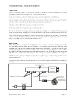
Nu-Way MOL 3400-410 Скачать руководство пользователя страница 26

FUEL PUMPS 

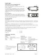
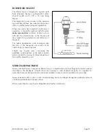
Suntec Series TV Pressure Regulating Valve 

(For use with Suntec series ‘T’ pumps) 

The TV valve is designed for use with the Suntec series ‘T’ fuel 
pumps, see diagrams. 
This separate pressure-regulating valve, which is installed in the 
nozzle line, is designed to keep constant pressure even if the 
output capacity is changed.  A built-in dampening device absorbs 
vibrations in the valve, effectively eliminating pulsations in the 
nozzle line. 


Pressure adjustment 

Remove the cap nut (1), washer (2) and loosen the locknut (4).  
Turning the screw (3) counter-clockwise will decrease the nozzle 
line pressure and visa-versa.  After adjustment, tighten the locknut 
and refasten the washer and cap nut. 
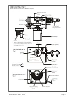
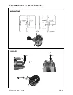
 

OIL PUMP DETAILS 

General Notes: 
Pump rotation is quoted by the direction of the pump shaft as viewed from the shaft side.  The direction 
arrow embossed on the face of the pump or pump nameplate is therefore the reverse of the quoted 
rotation. 
The Oil Pump is completely pre-piped as part of the pumping or pumping and heating set. 
Should the Oil Pump performance become suspect then a replacement unit should be obtained and the 
Oil Pump returned to determine its serviceability. 
Upon replacement refer to the pump bleeding instructions in the section 

Pre-firing Checks

 on page 15. 

Further details regarding the Oil Pump unit can be supplied on request. 
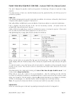
 

PUMP CAPACITY


HP 

Technik 

VBGR 

  = 

1150 

lt/h 

Suntec 

T2C 

   = 

1450 

lt/h 


SUNTEC Type T OIL PUMP   

Technical Data


General:  

Hydraulic 

data: 

Mounting: Flange 

mounting 

Nozzle pressure range: 

40 bar max  

Conn threads:  Cylindrical according to ISO 228/1 

Operating viscosity: 

4-450 cSt 

Shaft: 

20mm ø 

Oil temperature: 

0-140° max in the pump 

Weight: 

7.8 kg    


Inlet pressure - Light oil:    0.45 bar max vacuum to prevent 


air separation from oil 


 -  Heavy oil:  5 bar max 


Rated speed: 

3600 rpm max 


Starting torque: 

0.4 Nm 


MOL 3400-4100  Issue 2   10/08 


                                    Page 25


1. Suction 
2.  Pressure outlet and internal bypass plug 
3.  Vacuum or inlet pressure gauge port 
4.  Pressure gauge port 
5. Preheater 

cavity 

Содержание MOL 3400-410

Страница 1: ...Installation Maintenance Manual MOL 3400 4100 Oil Burner Tel 44 0 1905 794331 Fax 44 0 1905 794017 Email info nu way co uk Web www nu way co uk...

Страница 2: ...RNER CONTROL OPERATION MODULATING HIGH LOW 12 BURNER CONTROLS 13 Oil Pumping Units 13 Modulating Unit 13 COMMISSIONING GENERAL 14 Safety and Emergency Notes 14 Inspection 14 Pre Firing Checks 15 COMMI...

Страница 3: ...hese engineers should also be CORGI registered Nu way cannot be held responsible for any consequential damage loss or personal injury as a result of customers failing to follow these instructions or a...

Страница 4: ...ended for general assessment of the overall sizes of the burners and should not be used without reference to our engineering department for inclusion in drawings for installation purposes Certified di...

Страница 5: ...MOL 3400 4100 Issue 2 10 08 Page 4 BURNER AND COMPONENT IDENTIFICATION FOR MODULATING BURNERS All dimensions are in mm 6 3 4 1 4 9 10 11 13 7 8...

Страница 6: ...ck Release Connection 11 Burner Head Return Oil Quick Release Connection 12 Fan Inspection Cover 13 Ignition Transformer Burner Mounting Details On request MOL modulating burners can be supplied in th...

Страница 7: ...0 kW 3 x 40 Amp 26 35 Amp 6mm2 MOL 4100 36 6 Amp 7 5 kW 3 x 20 Amp 11 16 Amp 4mm2 MOL 4100 41 6 Amp 11 0 kW 3 x 32 Amp 19 27 Amp 6mm2 MOL 4100 44 6 Amp 15 0 kW 3 x 40 Amp 26 35 Amp 6mm2 Pumping Unit d...

Страница 8: ...ng burner can provide a turndown range of up to 3 1 The High Low version will be limited to a maximum of 2 5 1 Fuels MOL burners covered in this manual are designed to fire distillate fuel SITE CONDIT...

Страница 9: ...the total swept volume of the burner oil pumps connected to the supply system All oil supply pipes must be constructed and installed to comply with local conditions and appropriate codes of practice a...

Страница 10: ...and washers provided The pumping unit is supplied as a separate component to modes 1 and 2 and is inclusive of flexible pipes to make all the necessary oil connections Mode 3 On request MOL modulatin...

Страница 11: ...nimum 19mm and pressure rated for 42 kg cm2 600 psi All burners require a pump inlet pressure of 0 35 to 0 70 kg cm2 5 to 10 psi If a shut off valve is fitted in the inlet line a pressure relief valve...

Страница 12: ...burner component and pumping unit drawings on pages 4 13 Connect the oil supply to the burner pumping unit with reference to the oil system diagrams and pumping unit drawings on pages 10 19 Electrica...

Страница 13: ...29 of this handbook When the boiler control calls for heat the burner modulating unit will travel to the high flame position and interlock the control circuit An air pre purge will take place at this...

Страница 14: ...urner nozzle A return line from the back of the nozzle is connected to a spill regulating valve which regulates the oil pressure at the nozzle according to the position of an internal piston which is...

Страница 15: ...hat all manual fuel isolation valves are operable fully closed and leak tight Make all personnel involved in the commissioning aware of the location of the emergency fuel and electricity isolation poi...

Страница 16: ...to run through to lockout During this run check that the ignition spark is occurring and note the spill and line oil pressures at the moment of ignition Reset the sequence control and repeat the run...

Страница 17: ...mper is fully closed i e until all the slack is taken up on the cable Note Cams one and two control the high cam one and low cam two limits of the mechanism These are factory set and should not requir...

Страница 18: ...MOL 3400 4100 Issue 2 10 08 Page 17 MODULATING UNIT Cams shown in the Low Flame Position...

Страница 19: ...ing the inching switch Slowly turn the air pressure switch adjusting dial clockwise until the flame is extinguished The burner will go to lockout Turn the dial one division anticlockwise and reset the...

Страница 20: ...rt its cycle again It should lock out five seconds after the low flame solenoid valve is energised The air regulator should now be set to give a CO2 reading of 10 11 with a smoke number of 0 1 HIGH FL...

Страница 21: ...gineer shall prepare a report which shall contain the following 1 Details of any modifications made to the system together with revised drawings if necessary 2 Customer and plant details including any...

Страница 22: ...the burners Boiler Combustion Services Keep the boiler combustion surfaces and flueways clean Any accumulation of soot will decrease the efficiency of the boiler and increase the flue gas exit tempera...

Страница 23: ...nozzle is cleaned using non abrasive materials never use anything which may scratch the finely finished surfaces of the nozzle Nozzle life is approximately 5000 hours operation after which wear will...

Страница 24: ...the pre heater hot oil filter ensure that there is sufficient oil in the storage tank bleed the oil pump in case it is partially air locked Check to ensure that all stop fire valves in the supply line...

Страница 25: ...BURNER HEAD DETAILS ELECTRODE SETTING MOL 3400 4100 Issue 2 10 08 Page 24 MODULATING HIGH LOW 6 3 8 13...

Страница 26: ...re the reverse of the quoted rotation The Oil Pump is completely pre piped as part of the pumping or pumping and heating set Should the Oil Pump performance become suspect then a replacement unit shou...

Страница 27: ...pump with positive feed pressure an external bypass has to be made between the return port and the suction port Media The pump specification stipulates mineral based fuel oil or media of a correspond...

Страница 28: ...ly create a dangerous situation If a burner becomes troublesome then the assistance of a qualified engineer should be obtained To assist in his diagnosis notes should be made detailing the events lead...

Страница 29: ...witch or a contact has not been closed between control box terminals 12 and 4 or 4 and 5 Shut down of start up sequence because the OPEN signal has not been supplied to control box terminal 8 by the s...

Страница 30: ...be made in small increments with time given to see how the burner is reacting to the changed parameter Press and hold the PGM button down until the green set point figure changes to an AL the larger...

Страница 31: ...ition Fuel supply problem YELLOW NO FLAME End Lockout Solenoid valve defective Photocell dirty Photocell or circuit faulty YELLOW WITH FLAME End Locknut No voltage at terminal 20 When a burner failure...

Страница 32: ...e of the hexagonal nut section of the nozzle body as shown opposite Should any doubts arise concerning the suitability or performance of the burner nozzle please contact the Nu way Technical departmen...

Страница 33: ...elect a burner with a higher fan static pressure than would normally be chosen if the appliance has a high starting resistance Similarly when firing a reverse pass boiler up to 2 MW with a combustion...

Страница 34: ...erial No ________________ Burner Type ___________________ Rating ____________________ Spec No _________________ Serial No _______________ Nozzles ___________________ Oil Pump ________________ Commissi...

Страница 35: ...NOTES...

Страница 36: ...NOTES...

Страница 37: ...Enertech Limited P O Box 1 Vines Lane Droitwich Worcestershire WR9 8NA Tel 44 0 1905 794331 Fax 44 0 1905 794017 Email info nu way co uk Web www nu way co uk...

Отзывы: