BURNER CONTROLS
Burners are supplied with an integral control panel containing a sequencing control unit and the burner
switchgear. On steam boiler applications an auxiliary control panel containing boiler feed pump controls,
water level interlocks and alarms is available.
Oil Pumping Units
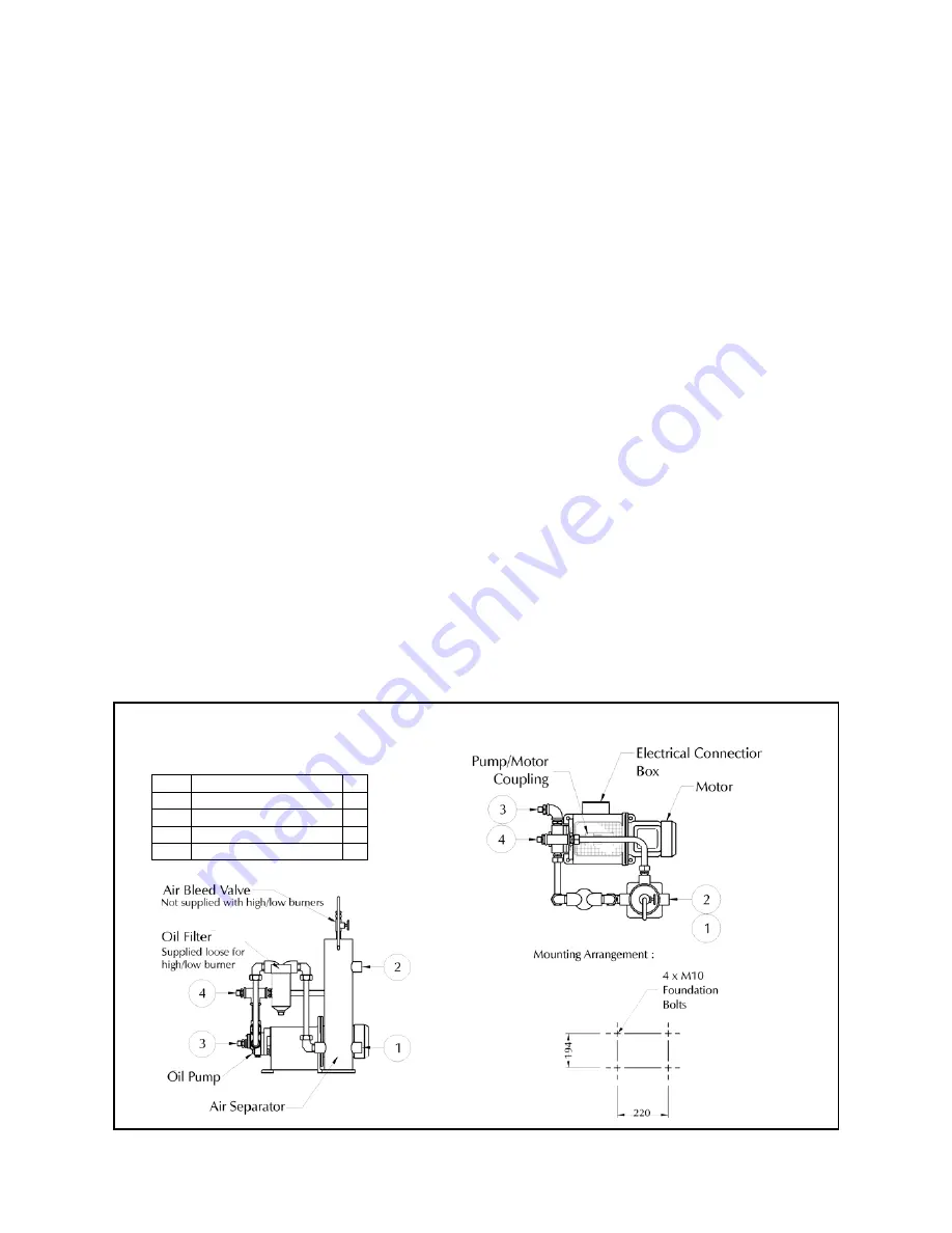
Standard burners are supplied with a floor-mounted pumping unit. Details of which are shown below.
On burners supplied in ‘compact’ configuration, the pumping equipment is mounted on the burner.
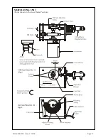
Modulating Unit
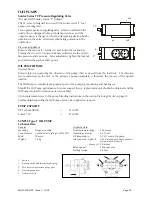
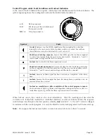
The modulating unit consists of a reversible servomotor, which is directly coupled to the camshaft of the
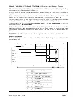
modulating unit. Two adjustable cams are mounted on this shaft, one of which is connected to a flexible
cable operating the burner air inlet control damper and is of the variable contour type (see fig 2 on page
17). The second cam is the modulating oil cam and is illustrated in fig. 1.
The
Burner Oil System
drawing on page 10 shows the hydraulic circuits. Oil for combustion is drawn from
the supply through a fixed displacement pump and supplied direct to the burner nozzle. A return line
from the back of the nozzle is connected to a ‘spill regulating valve’ which regulates the oil pressure at the
nozzle according to the position of an internal piston which is actuated by the oil control cam in the
modulating unit.
There is a well-defined relationship between the delivery of fuel through the nozzle and pressure behind
the nozzle, therefore movement of the oil cam ‘modulates’ the nozzle output and hence the output of the
burner.
The volume of air required for combustion must also be varied as the nozzle output varies, and this is done
by the air control damper, operated by a flexible steel cable connected to a lever system bearing against
the air control cam.
Once the oil has been adjusted as described in the
Commissioning
procedure section of this handbook, the
profile of the air cam is adjusted to give the desired combustion conditions by turning the thumbscrews
under the cam in or out as the burner is ‘inched’ through its firing range.
The air control damper is spring-loaded ‘open’ for safety in the event of cable failure.
MOL 3400-4100 Issue 2 10/08
Page 13
OIL PUMPING SET
Pipework Connections
Item Description R”
1 Oil Inlet Connection
1
2 Oil Return Connection
1
3 Burner Oil Feed
3/4
4 Burner Oil Return
3/4


