


ROUTINE MAINTENANCE OF MOL BURNERS
General
It is vitally important that personnel responsible for the day to day operation and maintenance of the plant
are instructed by the commissioning engineer on the basic function of the burner, as well as the need for
routine maintenance and daily checking of burner operations.
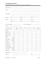
Final adjustments, which will have been made during the commissioning, must be recorded on the
Commissioning Sheet
at the back of this manual and in the appliance
log book
. A copy of the
commissioning data
must
be sent to the appliance manufacturer.
The burner should be kept clean inside and out. It will be more reliable, and if an oil leak occurs it will be
spotted more readily.
Daily Checks
Inspect the burner daily to check if there is any variation from the correct operating sequence, as follows:
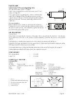
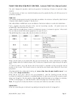
Check the oil pressure on the nozzle line gauge. This should be 27.8 bar (400 psi). If the oil pressure is
low, then check the oil supply system, stop/fire valves, ring main pumps, etc.
Check the spill pressures. If these are low it may indicate that the oil nozzle filter is clogged.
If there is an inspection window on the appliance through which the ignition spark and flame can be
observed, ignition and flame should be inspected and any irregularities that are observed should be
rectified, i.e. nozzle/electrodes cleaned and any deposits removed from the inside of the flame tube and
diffuser.
Replenishing the Fuel Supply
It is usual practice to shut boiler(s) off whilst delivery of fuel is being made and allow approximately 30
minutes for any sediment to settle before restarting the burners.
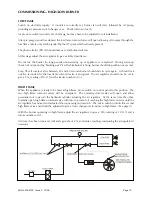
Boiler Combustion Services
Keep the boiler combustion surfaces and flueways clean. Any accumulation of soot will decrease the
efficiency of the boiler and increase the flue gas exit temperature. Always cover up the burner during
boiler cleaning operations.
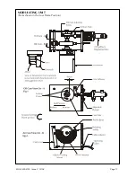
Inner Assembly Removal – High/Low Burners
The inner assembly, comprising the nozzle block and diffuser plate, can be removed through the burner
casing. First switch off the electricity supply to the burner, remove the burner casing top cover (eight
screws).
Disconnect the Allen screw securing the outer manifold to the inner manifold, located on the right-hand
side of the burner casing.
Note that these two manifolds are sealed together by ‘O’ rings.
The solenoid valves, pressure gauges, etc, are now released from the outside of the burner casing. They
may be supported, while the burner inner assembly is removed, by entering the Allen screw through the
outer manifold into the (tapped) boss provided for the purpose in the burner casing immediately below the
normal manifold location.
Remove the two nuts securing the inner manifold to the inside of the burner casing.
By grasping the inner assembly pipes the complete inner assembly/diffuser can be withdrawn from the
casing.
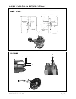
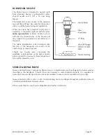
The diffuser plate is mounted on a bracket clamped to the nozzle assembly.
The front of the nozzles should be set approximately 12mm (½”) behind the diffuser face.
The diffuser should be set 102mm (4”) back from the front of the flame tube. The position can be
adjusted if necessary. If the burner has one low flame nozzle (the upper one) the ignition electrodes are
set on this nozzle. If there are two low flame nozzles the ignition electrode should be set over the top
left-hand nozzle (as viewed from the front, or boiler side of the burner).
MOL 3400-4100 Issue 2 10/08
Page 21