


THE BURNER IS NOW READY TO BE COMMISSIONED
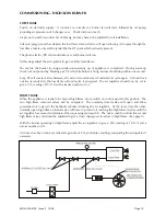
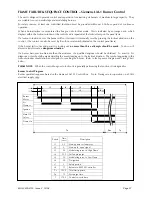
COMMISSIONING - MODULATING BURNER
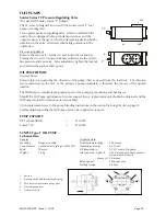
Hand Auto Selector Switch
This switch must always be in the
‘Auto’
position when the burner is required to start. The
‘Hand’
selection can be made immediately the burner has started to fire.
Should the burner be left in the
‘Hand’
position it will
NOT
modulate until the
‘Auto’
position is selected.
Commissioning the Burner
New MOL 3400 & 4100 modulating burners are generally supplied against the firing specification of the
appliance. In this case the system and spill pressure may be pre-set and require checking and minor
adjustments only. The following section describes how to set up the modulating cam box unit from a
‘scratch’ situation.
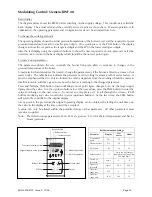
The modulating cam layshaft can be rotated by hand using the gearbox disengagement lever in the drive
servomotor.
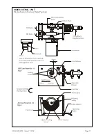
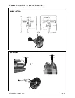
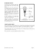
Ensuring that the modulating cam arrangement is in the low flame position, adjust the oil cam (see fig 1,
page 17) so that it gives approximately 1.5mm throw (3mm stoke and lock in position).
Check to ensure that the spill valve push rod bears lightly against the oil cam.
Turning to the air cam (fig.2) rotate the thumbscrews in or out so that they give a reasonable amount of
adjustment in each direction. Adjust the flexible cable (at either end if necessary) until the air inlet
damper is fully closed (i.e. until all the slack is taken up on the cable).
Note:
Cams one and two control the high (cam one) and low (cam two) limits of the mechanism. These are
factory set and should not require any adjustment. However, in extreme circumstances the angle of
rotation can be reduced by adjustment of the appropriate cam. Any adjustment made will alter the oil
spill pressure.
Now adjust the thumbscrews to give a small opening of the air damper at low flame.
Uncover and replace the photocell. Reset the sequence control and allow the burner to start.
Immediately the burner starts, switch the hand/auto selector switch to the ‘hand’ position and hold low
flame until the appliance is ready to accept high flame. During this period, check and adjust the low
flame oil throughput.
Check the flame visually. If the flame is dirty, adjust the air cam thumbscrews until the flame becomes
clean.
After a suitable delay, inch the camshaft to the high flame position (i.e. through 180) by means of the
inching switch on the control panel. Adjust the air cam profile by means of the thumbscrews until the
air damper is now fully open. At this stage it will be found that all of the thumbscrews between low and
high position will require adjusting so as to avoid over stressing the cam profile band.
Once this has been done, there should be a fairly smooth profile between low and high positions.
Ensure that the flame is visually clean throughout the modulation range at all times.
MOL 3400-4100 Issue 2 10/08
Page 16