FAULT FINDING
If the Burner Fails to Start
Make sure that all the thermostats and switches in the control circuit are in the ‘made’ position and that
the oil pre-heater ‘excess limit’ thermostat has not tripped. Reset if required. Check that the low oil
temperature thermostat is set correctly for the appropriate fuel.
Check that the electricity supply to the burner is ‘live’ and that the control and main circuit fuses are intact.
If a fuse is found to be ‘blown’ then the cause should be investigated and rectified before proceeding
further.
On steam boilers, check that the ‘water level interlocks’ are in the ‘made’ position.
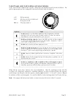
If the burner is found at lockout (red lockout lamp illuminated)
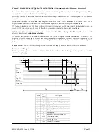
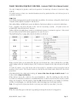
Reset the burner and observe the starting sequence. (make reference to the
Sequence Diagram and Timing
Charts
for the Flame Failure controls on page 27 for further information
.
Check the fan and oil pump motor overloads and reset if necessary.
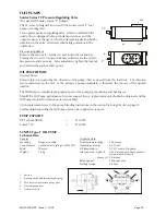
Check the operation of the air pressure switch. Failure of the switch to operate prevents the oil pump from
starting.
Flame Occurs Followed by Immediate Lockout
Check the PE cell and the air regulator for correct operation. Check that the oil pressures are correct. If
necessary, check and clean the pre-heater hot oil filter, ensure that there is sufficient oil in the storage tank,
bleed the oil pump in case it is partially air-locked. Check to ensure that all stop/fire valves in the supply
line are fully open. Check residual fuel oil temperature – check the ring main for correct operation in
respect of temperature and pressure.
The Burner Starts With The Correct Oil Pressure But No Flame Appears
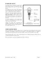
Check the ignition system, HT lead connections, electrode gap and the condition of the electrode
insulators. Check that the nozzle cut-off is functioning and that the air damper cable is not broken or
disconnected (the air regulator will be fully open).
It is important to note that continued re-setting of
the burner should be avoided as this can lead to a dangerous situation.
Modulating System
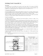
If malfunction of the modulating controller RWF 40 is suspected, check that only compatible components
such as the range insert and pressure/temperature detector have been used. If problems persist then
replacement of the unit should be considered.
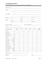
Burner Commissioning Sheet
This manual contains a record of the essential information and will have been completed by the
commissioning engineer with individual details of the burner. These details should be verified periodically
and adjusted if variations are noted. Commissioning details must also be record in the
appliance logbook
.
MOL 3400-4100 Issue 2 10/08
Page 23


