


All personnel concerned with commissioning and/or operation of MOL burners shall
familiarise themselves with the information presented in this section.
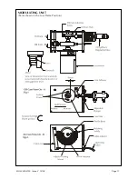
BURNER OPERATION - MODULATION
Burner Description
Nu-way MOL modulating series fully automatic oil burner units are of packaged design and meet relevant
National and International standards based on the ISO system of measurement and fastening.
A system of pressure atomisation employing a single spill-back nozzle is used throughout the range. If the
burner is equipped with the
Nu-way Electronic Cam Modulating (ECM)
system, then reference should
also be made to the supplementary documentation supplied with this handbook. In the case references to
the RWF40 Universal Controller and Modulating Unit within this handbook can be ignored.
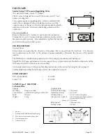
The standard method of operation is based on the Siemens RWF40 Universal Controller, which has been
designed for use in oil and gas fired installations, where it provides temperature or pressure control of
modulating burners with continuously adjustable fuel throughput.
The control output of the RWF40 is a potential free 3-position switch, which is used for the control of
reversible motors. The control signals for the Open (Y1) and closed (Y2) are indicated on the controller
face by light emitting diodes.
For further information on the RWF40 and its associated components, please refer to the data provided on
page 29 of this handbook.
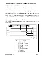
When the boiler control calls for heat, the burner modulating unit will travel to the ‘high flame’ position
and interlock the control circuit. An air pre-purge will take place at this position for a pre-determined
period, at the end of which the burner sequence controller will stop until the modulating unit has travelled
to the ‘low flame’ position and interlocked the control circuit again. The sequence control will now
recommence its operational cycle and the burner will light and remain at low flame until the high flame
release signal is given by the sequence control.
The modulating unit will now move to high flame and remain at this position until the desired boiler
temperature/pressure is attained. From this stage the modulating unit will commence to move towards the
low flame position between low and high flame.
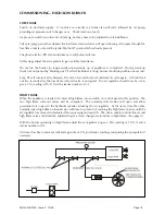
BURNER OPERATION – HIGH/LOW
The oil system operates at constant pressure and utilises four nozzles in order to minimise nozzle size, thus
producing the fine atomisation necessary for efficient combustion.
The air regulator is of a rotary type and is hydraulically actuated. Access by removing the top cover from
silencer box and air adjustments by set pins operating against stop on moveable part of regulator.
An adjustable microswitch is actuated by the moving air regulator. The microswitch controls the air/oil
phasing on the change from low to high flame. The switch also proves that the air regulator is moving
before high flame is allowed to spray. The microswitch controls an additional, normally open, solenoid
valve.
MOL 3400-4100 Issue 2 10/08
Page 12