


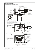
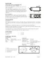


Check the oil consumption. If this is not correct for the full burner rating, the oil cam must be adjusted as
follows:-
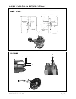
a. Inch the burner to low flame and note the spill pressure
b. To increase the minimum rate, adjust as shown in fig.1.
c. Adjust the cam to give more eccentricity for more oil at high flame, and vice-versa.
d. Return to the minimum setting and compensate for any changes.
e. Inch the burner to high flame and again check the oil flow.
Continue to repeat a. to d. until the high flame oil rate is correct.
When a satisfactory setting has been achieved, lock the air cam thumbscrews with the grubscrews fitted in
the face side of the cam body. Refit the Modulating unit access cover.
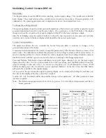
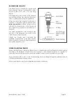
Check the function of the air pressure switch:
Switch off the electrical supply to the burner.
Remove the air pressure switch cover. Fit a manometer to the pressure switch to check the actual air
pressure against the pressure switch dial setting.
Switch on the electrical supply and allow the burner to establish low flame.
Select ‘Hand’ control and ensure that the burner is at low flame by using the inching switch.
Slowly turn the air pressure switch adjusting dial clockwise until the flame is extinguished. The burner
will go to lockout.
Turn the dial one division anticlockwise and reset the burner lockout. The burner will now continue
through its cycle until flame is established or the burner goes to its lockout position. If the burner goes
to lockout repeat the procedure one division per burner cycle until flame is established. Once
successful turn the dial a further two divisions anticlockwise.
Switch off the burner electrical supply, replace the air pressure switch cover and remove the
manometer.
If the burner control is inclusive of Low, Excess Low and High Water interlocks and alarms, test that these
function correctly. Ensure that the boiler feed pump switchgear provided in the panel is operating
satisfactorily.
Adjust the boiler to attain the correct working pressure/temperature and adjust the on/off and limit
instruments to the desired values.
Switch the Hand/Auto selector switch to ‘Auto’. The plant is now under the control of the
pressure/temperature controllers for modulation and the on/off and high limit instruments for control.
Finally check ancillary controls and equipment such as damper interlocks etc.
MOL 3400-4100 Issue 2 10/08
Page 18